Voltage varying-regulating circuit, voltage varying-regulating set and intelligent electricity-saving device

A technology of a power-saving device and a voltage-regulating circuit, which is applied in the direction of adjusting electrical variables, control/regulating systems, and output power conversion devices, etc. Long-term stable operation and the effect of reducing self-consumption

Inactive Publication Date: 2009-09-09
深圳诺尔生态环境股份有限公司
View PDF0 Cites 17 Cited by
  • Summary
  • Abstract
  • Description
  • Claims
  • Application Information

AI Technical Summary

Problems solved by technology

[0007] (1) Since the total working current of the power saver is I=IR+IT, and the current of IT is small, the larger current IR passes through point B and passes through RL to form a closed loop, so when KM, KM1, and KM2 are switched, the touch The point flow current is large, it is easy to damage the contactor, which seriously affects the stability and service life of the power saver itself;
[0008] (2) Since the load RL must be disconnected from the power supply circuit before being connected in each switching, this will cause the load RL to be powered off, and the power-off time is the time for the two contactors to operate
In this case, if the load RL is a lighting load, it is easy to cause the light source to be turned off and then restarted, which is the phenomenon of "flash" in the power saving industry.
This phenomenon will cause greater damage to lighting fixtures;
[0009] (3) When the voltage is adjusted, due to the "flash" phenomenon of the load and the large switching current of the contactor, it is impossible to set multi-level automatic adjustment in actual use, which seriously reduces the intelligence and applicability of the power saver

Method used


Image

  • Voltage varying-regulating circuit, voltage varying-regulating set and intelligent electricity-saving device
  • Voltage varying-regulating circuit, voltage varying-regulating set and intelligent electricity-saving device
  • Voltage varying-regulating circuit, voltage varying-regulating set and intelligent electricity-saving device

Examples


Embodiment Construction

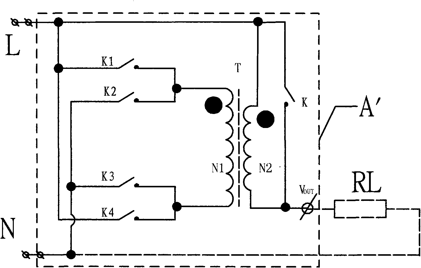
[0022] The voltage-changing and regulating circuit, voltage-changing and voltage-regulating and power-saving device provided by the embodiments of the present invention can reduce the self-consumption of the circuit by controlling the bypass switch K, and enable the voltage regulating device to operate stably for a long time.

[0023] The technical solutions of the embodiments of the present invention will be described in detail below in conjunction with the accompanying drawings.

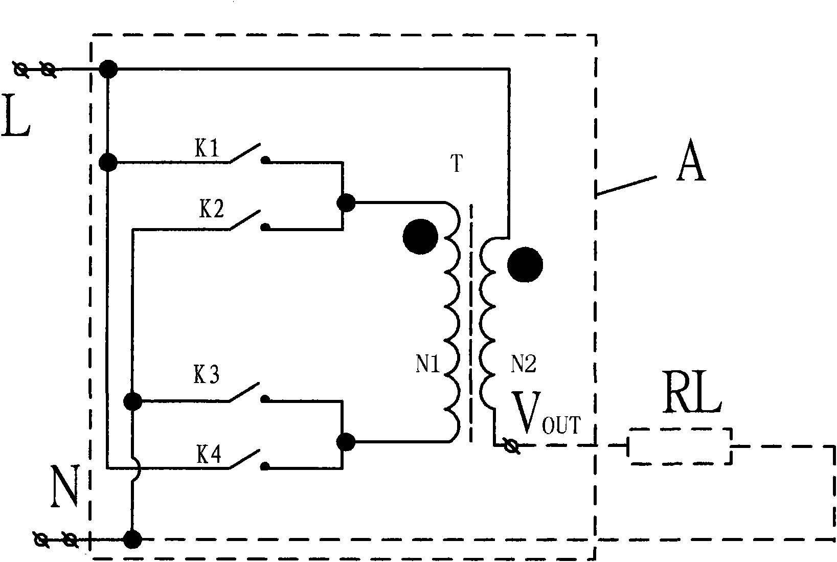
[0024] figure 2 The first kind of voltage-changing and voltage-regulating circuit provided for the embodiment of the present invention; the voltage-changing and voltage-regulating circuit such as figure 2 As shown, it includes a no-load circuit A for voltage transformation and regulation, and the no-load circuit includes a switch K1, a switch K2, a switch K3 and a switch K4, a transformer T, wherein the switch K1 and the switch K2 are connected in parallel, and one end of the switch K1 and the sw...


PUM


Abstract

The embodiment of the invention relates to the field of power electronics, and provides a voltage varying-regulating circuit. The voltage varying-regulating circuit comprises a voltage varying-regulating idle circuit. The idle circuit comprises a switch K1, a switch K2, a switch K3, a switch K4 and a transformer T, wherein the switch K1 and the switch K2 are connected in parallel; one end of the switch K1 and one end of the switch K2 are connected with the anode of the primary side of the transformer; the switch K3 and the switch K4 are connected in parallel; one end of the switch K3 and one end of the switch K4 are connected with the cathode of the transformer; the other end of the switch K1 and the other end of the switch K4 are connected to one pole of an input end; the other end of the switch K2 and the other end of the switch K3 are connected to the other pole of the input end; and a load RL is connected in series between the output end VOUT of the secondary side of the transformer T and an N pole. The invention also provides a corresponding voltage varying-regulating set and an electricity-saving device. As the circuit reduces own consumption, a voltage regulating device can operate with long-term stabilization.

Description

technical field [0001] The invention relates to the field of power electronics, in particular to a voltage-changing and voltage-regulating circuit, a voltage-changing and voltage-regulating group and an intelligent power-saving device with a voltage stabilizing function. Background technique [0002] State-of-the-art power savers such as figure 1 As shown, including bypass contactor KM, 205V output control contactor KM1 (low power-saving gear); 195V output control contactor KM2 (high power-saving gear); tuned output autotransformer T (phase modulation line), Load RL. This prior art solution achieves the purpose of changing the output voltage by adjusting the number of secondary (output end) coils of the autotransformer. In terms of control principle, KM is interlocked with KM1 and KM2, and KM1 and KM2 are interlocked. The L terminal is connected to the mains phase line (live wire), the B point is connected to the load RL, and N is the neutral line. The working process is a...

Claims


Application Information

Patent Timeline
Patent Type & Authority Applications(China)
IPC IPC(8): H02M5/12H02P13/06G05F1/14
Inventor 陈建业刘维春
Owner 深圳诺尔生态环境股份有限公司
Why Eureka
Try Eureka