
Network illumination control system

A lighting control system and network technology, applied in lighting devices, store-and-forward switching systems, light sources, etc., can solve problems such as poor flexibility, poor automatic control capabilities, and limited number of objects, and achieve high flexibility and strong automatic control capabilities Effect

Inactive Publication Date: 2009-09-09
CCDI INT SHENZHEN DESIGN CONSULTANTS
View PDF3 Cites 2 Cited by
  • Summary
  • Abstract
  • Description
  • Claims
  • Application Information

AI Technical Summary

Problems solved by technology

The control of lighting depends on the server, the automatic control ability is poor, and the flexibility is poor
And the existing communication protocol is developed on the basis of DMX512, the number of objects that can be controlled is limited, and the performance of communication security, speed, bandwidth, etc. is not high

Method used


Image

  • Network illumination control system
  • Network illumination control system
  • Network illumination control system

Examples


Embodiment Construction

[0015] In order to solve the problems of poor automatic control ability and low flexibility in the lighting control system in the prior art, the present invention provides a networked lighting control system, which will be described in detail below with reference to the accompanying drawings.

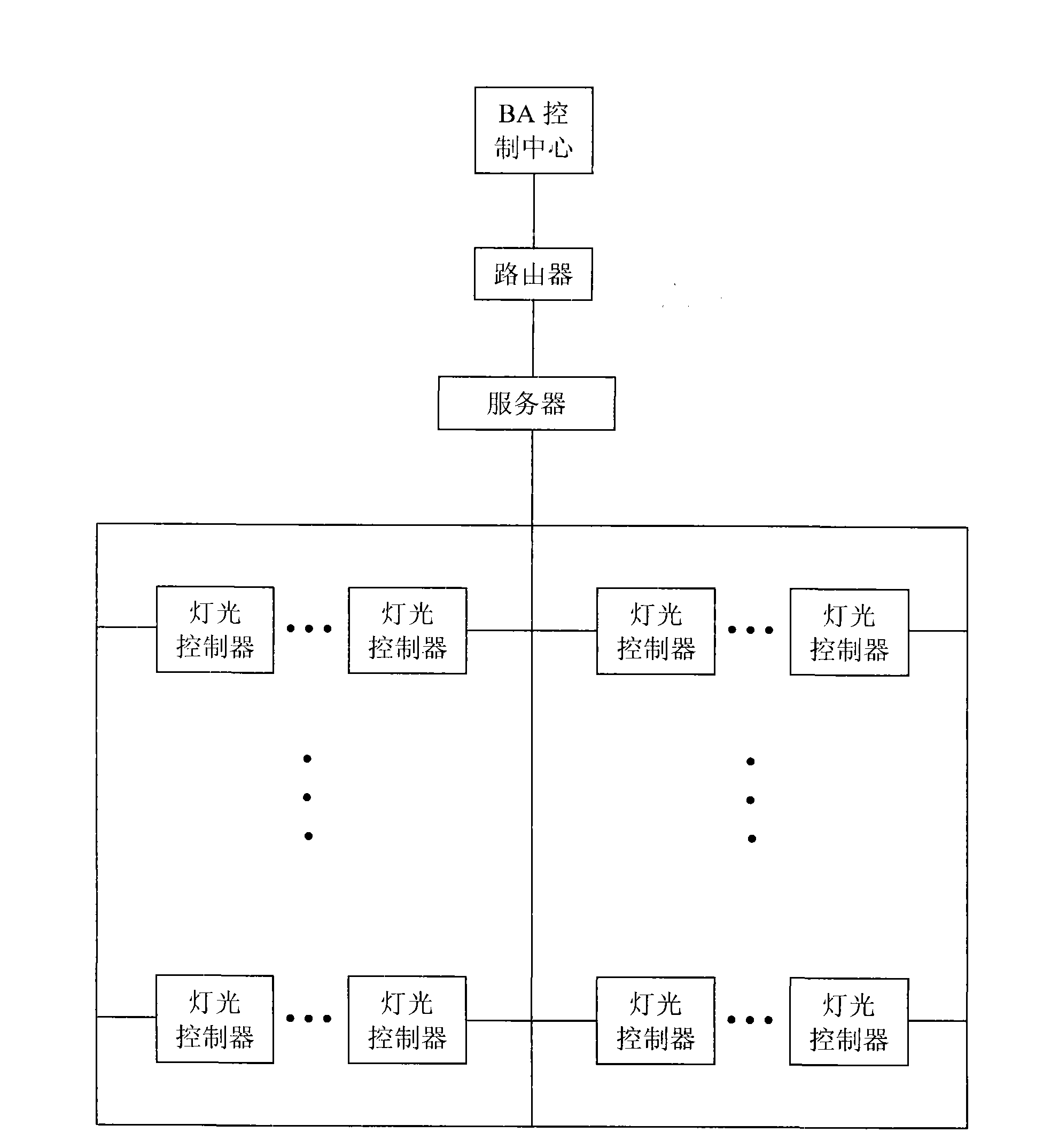
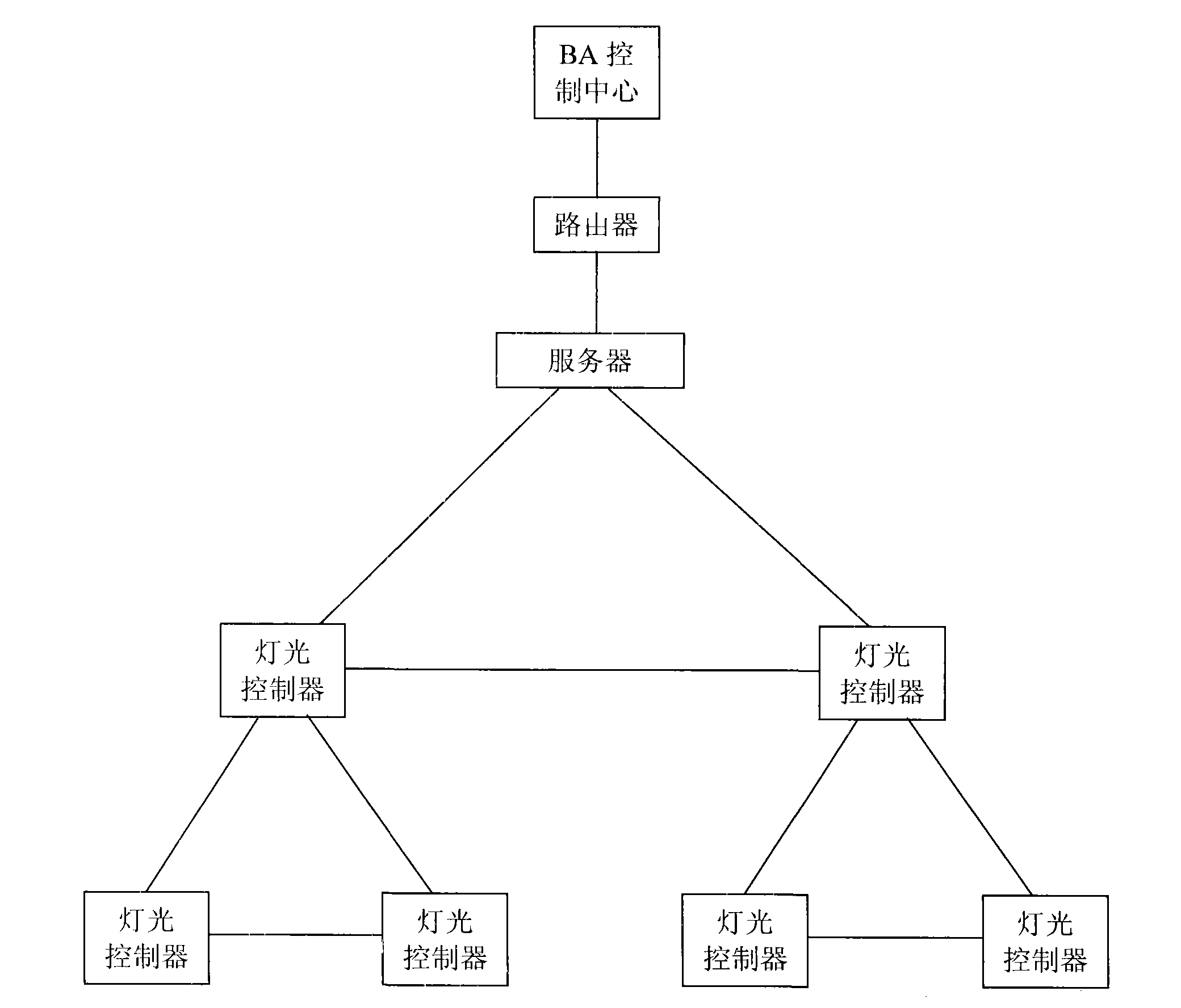
[0016] Such as figure 2 As shown, the network lighting control system of the present invention includes a server and a lighting controller, and the lamps are connected to the lighting controller (the lamps are omitted in the figure). The connection mode between the lighting controllers is a peer-to-peer network topology, and the server is electrically connected to at least one lighting controller.

[0017] The control information of the lamps (ie, the data of the lighting scene file) is stored in the server, and the lighting controller obtains the control information from the server, and then uses it to control the on-off and color of the respective connected lamps. In the peer-to-pee...


PUM


Abstract

The invention discloses a network illumination control system, belongs to the technical field of illumination control, and is designed to solve the problems of poor automatic control capacity and low flexibility of the illumination control system in the prior art. The network illumination control system comprises a server, at least three light controllers and lamps connected to the light controllers; the connecting mode of the at least three light controllers adopts a peer-to-peer network topology structure; and the server is electrically connected with at least one of the at least three light controllers; and the server sends lamp control information to the light controllers, the light controllers control the lamps according to the control information, and the light controllers perform communication mutually and provide services. The network illumination control system is suitable for light control places, in particular places with numerous lamps and high control requirements.

Description

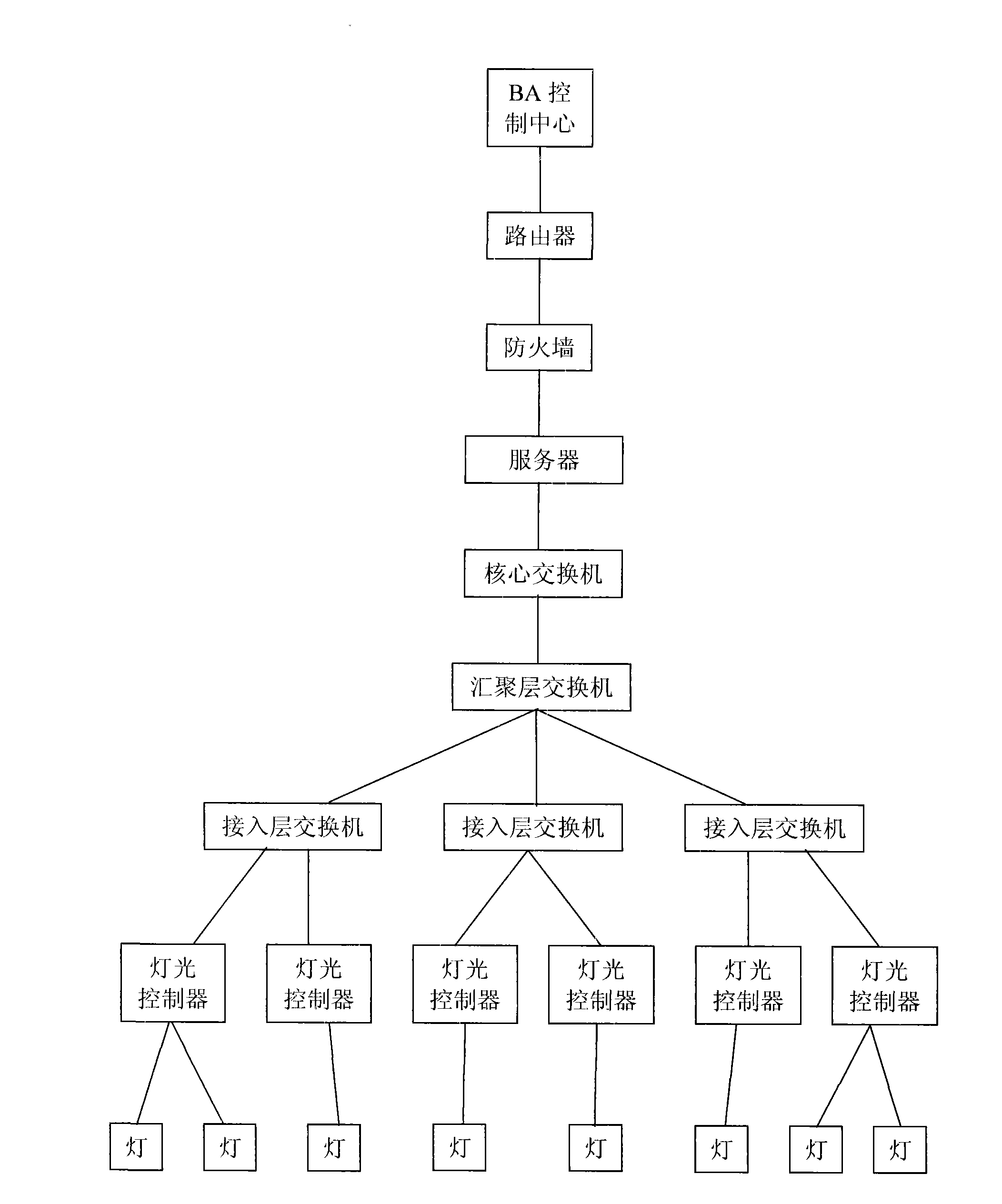
technical field [0001] The invention relates to a lighting control system, in particular to a network lighting control system. Background technique [0002] The existing lighting control network mainly adopts the master-slave structure, such as figure 1 As shown, a plurality of lighting controllers are respectively connected to a plurality of lamps, and the lighting controllers are connected to the server through a switch. A switch is used to forward information between the server and the light controller. When the number of lamps is large, more lighting controllers are required. However, the number of ports used by the switch to connect to the lighting controller is limited. At this time, the switch needs to form a multi-layer structure, generally three layers. The bottom layer is the access layer switch, which is used to connect the lighting controller; the middle layer is the aggregation layer switch, which is used to connect the access layer switch; the uppermost laye...

Claims


Application Information

Patent Timeline
Patent Type & Authority Applications(China)
IPC IPC(8): H05B37/02H04L12/28H04L12/54
Inventor 李兴林
Owner CCDI INT SHENZHEN DESIGN CONSULTANTS
Learn More