Connector

A technology of connectors and connecting parts, which is applied in the direction of connection, fixed connection, and parts of connection devices, etc. It can solve the problems of limited increase in installation density, reliability of easy-to-disengage contact, difficulty in miniaturization of devices, etc., and achieves increased installation density, High contact reliability and effect of improved contact reliability

Active Publication Date: 2009-09-09
ORMON CORP
View PDF1 Cites 11 Cited by
  • Summary
  • Abstract
  • Description
  • Claims
  • Application Information

AI Technical Summary

Problems solved by technology

[0004] However, in the above-mentioned connector, since the contact portion 52 is only arranged on the upper surface of the front end of the FPC22, the improvement of the mounting density is limited, and the device is not easy to be miniaturized.
In addition, for example, when wiring is routed through a labyrinth-like space inside an electronic device to connect one connector to another connector, there is a problem that it is easy to come off and the contact reliability is low.

Method used


Image

  • Connector
  • Connector
  • Connector

Examples


Embodiment Construction

[0061] Refer to Figure 1~Figure 14 The embodiments of the present invention will be described.

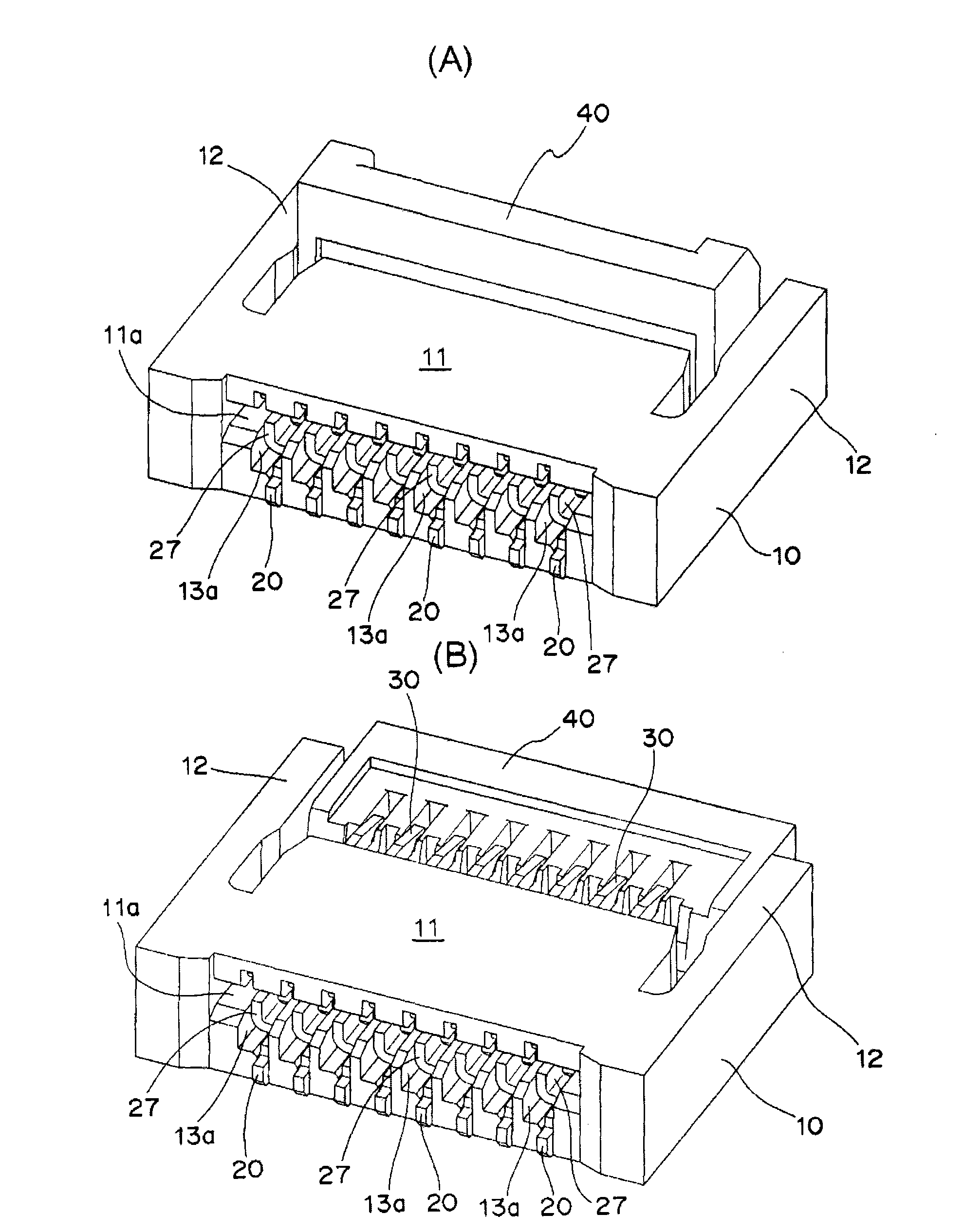
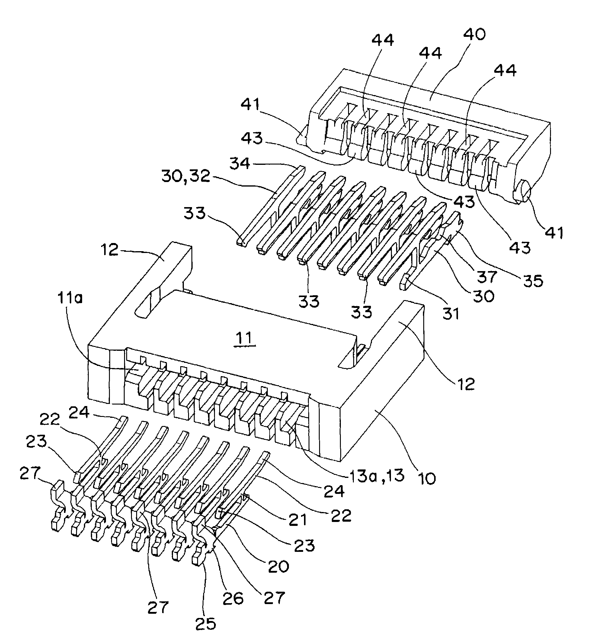
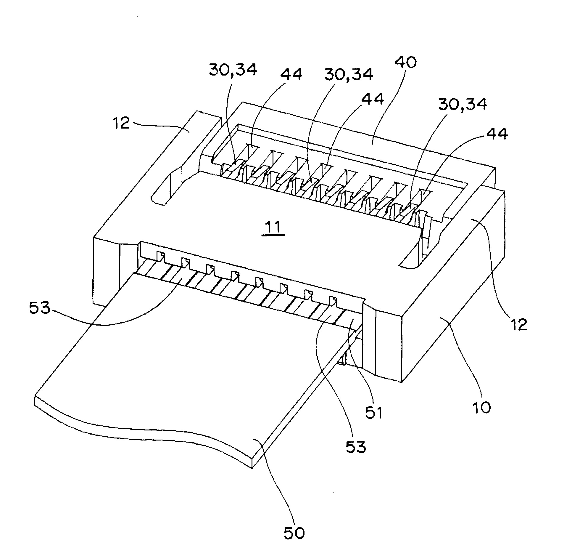
[0062] Such as Figure 1 ~ Figure 3 As shown, the connector 10 of the first embodiment is roughly composed of a base 11, a first connection terminal 20, a second connection terminal 30, and an operating lever 40.

[0063] Such as Figure 5 As shown in (B), the base 11 has elastic arms 12 and 12 extending in parallel from one side edge to the back side of both end surfaces of the base 11, respectively. On the inward surface of the elastic arm portion 12, a guide tapered surface 12a is formed on the front end edge portion, and a shaft support slit 12b is formed on the back side thereof. In addition, such as Figure 5 As shown in (A), the base 11 is provided with an opening 11a on the front surface into which the front end 51 of the FPC 50 described later can be inserted, and a first insertion hole 13 with a stepped portion 13a for fitting is arranged side by side at a predetermined pitc...


PUM


Abstract

The invention provides a connector which can be miniaturized easily while exhibiting high mounting density and high contact reliability. The connector comprises a base (11) having in the front an opening (11a) for receiving the tip portion (51) of an FPC (50) and first and second insertion holes (13, 14) juxtaposed alternately in the front and the rear, a first connection terminal (20) inserted into the first insertion hole (13) and having a first movable contact (23) which can come into pressure contact with the first joint (52) of the FPC (50), a second connection terminal (30) inserted into the second insertion hole (14) and having a second movable contact (33) which can come into pressure contact with the second joint (53) of the FPC (50), and an operating lever (40) supported rotatably by the base (11) and having first and second operating portions (42, 43) capable of operating the first and second connection terminals (20, 30) and juxtaposed alternately at the edge on one side.

Description

Technical field [0001] The present invention relates to a connector, and more particularly, to a connector that is connected to a connection portion provided in parallel on the upper and lower surfaces of a front end portion of a flexible printed circuit board (hereinafter referred to as "FPC"). Background technique [0002] Conventionally, as a connector, for example, as shown in Patent Document 1, the contact portions 30 and 30 of the contacts 14 and 16 are brought into contact with the contact portions 52 and 52 arranged in a zigzag shape on the upper surface of the FPC 22 to connect the FPC 22. . [0003] Patent Document 1: (Japan) Unexamined Patent Publication No. 2004-221067 [0004] However, in the above-mentioned connector, since the contact portion 52 is merely arranged on the upper surface of the front end portion of the FPC 22, the improvement in the mounting density is limited, and the device is not easily miniaturized. In addition, for example, when wiring is routed ...

Claims


Application Information

Patent Timeline
Patent Type & Authority Applications(China)
IPC IPC(8): H01R12/24H01R13/629
CPCH01R12/774H01R12/88H01R13/62988H01R12/77H01R12/51H01R13/629
Inventor 逸见幸伸寺西宏真
Owner ORMON CORP
Why Eureka
Try Eureka