Remote control key

A technology of remote control keys and instructions, applied in the direction of keys, signal transmission systems, instruments, etc.

Inactive Publication Date: 2009-09-16
HONG FU JIN PRECISION IND (SHENZHEN) CO LTD +1
0 Cites 10 Cited by

AI-Extracted Technical Summary

Problems solved by technology

If you don't confirm it, the user will always be worr...

Abstract

The invention relates to a remote control key, which comprises a button, an instruction generator and an emitter. The button is used for responding to user action to generate a locking instruction and an unlock instruction, and sending the locking instruction and the unlock instruction to the instruction generator; the instruction generator is used for generating a locking signal and an unlocking signal according to the locking instruction and the unlock instruction and sending the locking signal and the unlocking signal through the emitter in a wireless mode; the remote control key also comprises a record unit and an indicating unit; the record unit is used for storing key information comprising unlocking and locking when a user presses the button finally; and the indicating unit is used for responding to the user action and recording the key information according to the record unit to send a prompting massage so as to prompt the user that the instruction generated by the last button press is unlocking or locking instruction. When using the remote control key and a remote control method thereof to control an electronic lock, although the user leaves the electronic lock, the user still can know that whether the button pressed finally is the locking button or not through the prompting massage sent out after the operation on the remote control key.

Application Domain

Transmission systemsKeys +1

Technology Topic

Embedded systemRemote control +1

Image

  • Remote control key
  • Remote control key
  • Remote control key

Examples

  • Experimental program(1)

Example Embodiment

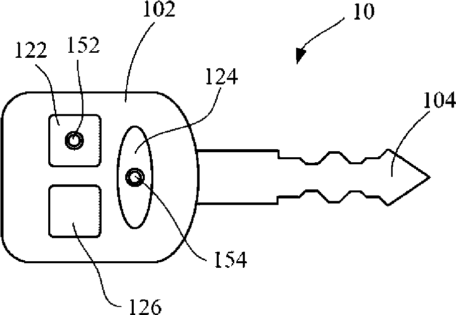
[0022] see figure 1 , which is a schematic diagram of the appearance structure of the remote control key 10 in the first preferred embodiment. The fob 10 includes a controller 102 and a rack 104 connected thereto. The controller 102 is used to send wireless control signals to remotely control the switch of the controlled lock, such as the switch of the door lock. The rack 104 is used for inserting into the corresponding lock hole to perform mechanical switch lock. In other embodiments, the rack 104 may not be present. The controller 102 includes a lock button 122 , an unlock button 124 , a detection button 126 , and two indicator lights 152 , 154 . Two indicator lights 152 and 154 are respectively arranged on the lock button 122 and the unlock button 124 .
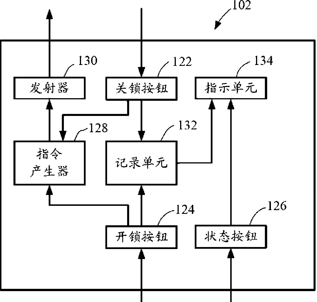
[0023] Please also see figure 2 , which is figure 1 The shown functional block diagram of the controller 102 in the remote control key 10 includes a lock button 122 , an unlock button 124 , a detection button 126 , an instruction generator 128 , a transmitter 130 , a recording unit 132 and an indication unit 134 .
[0024] The lock button 122 and the unlock button 124 are respectively used to generate a lock command and an unlock command in response to user operations, and send the generated lock command and unlock command to the command generator 128 .
[0025] The command generator 128 is used to generate a lock signal and an unlock signal according to the lock command and the unlock command, and transmit them wirelessly through the transmitter 130 to control the locked switch. Such as controlling the switch of the car door.
[0026] The recording unit 132 is used for storing key information of the last user pressing the lock button 122 and the unlock button 124 . For example, "0" indicates that the last button pressed by the user is the lock button 122 , and "1" indicates that the button last pressed by the user is the unlock button 124 . The recording unit 132 can be implemented with storage elements such as registers. Because there are only two states of two buttons, the recording unit 132 can also be realized by an electronic switch, and the two states correspond to the on and off states of the electronic switch respectively.
[0027] The detection button 126 is used to receive a user operation to generate a detection instruction.
[0028] The indicating unit 134 is used for responding to the detection instruction, and sending prompt information according to the key information recorded by the recording unit, so as to remind the user that the last button pressed is the lock button 122 and the unlock button 124 . In this embodiment, the indicating unit 134 is figure 1 Shown are two indicator lights 152 , 154 respectively provided on the lock button 122 and the unlock button 124 . When the last button pressed by the user is the lock button 122 , the prompt message is that the indicator light 152 lights up. When the last button pressed by the user is the unlock button 124 , the prompt message is that the indicator light 154 lights up. Wherein, the light-emitting mode of indicator light 152,154 also can be reversed, and promptly indicator light 152 indicates that the button that user presses at last is unlock button 124 when indicator light 152 is illuminated, and indicator light 154 indicates that the button that user presses at last is lock button 122 when light-emitting. . The positions of the indicator lights 152, 154 can be changed arbitrarily. In other implementation manners, the indicating unit 134 can also be in other forms, such as sounding from a speaker, displaying on a display screen, or even vibrating, as long as it can show two states.
[0029] When using the above-mentioned remote control key 10 to carry out the switch control of the electronic lock, even if the user leaves the electronic lock, he can also know whether the button he pressed last is the lock button by pressing the light-emitting situation of the indicator lights 152 and 154 after the detection button 126 is pressed. 122, that is to say, to judge whether the electronic lock is locked or not. For example, it is not necessary to return to the car to confirm whether to judge whether to lock the car door, which greatly facilitates the user.
[0030] see image 3 , which is a schematic diagram of the appearance structure of the remote control key 20 in the second preferred embodiment. remote control key 20 with figure 1 The difference of the remote control key 10 shown is that there is only one indicator light 228 on the remote control key 20 , and its light-emitting and non-light-emitting states are used to indicate that the last buttons pressed by the user are the lock button 224 and the unlock button 226 .
[0031] see Figure 4 , which is a schematic diagram of the appearance structure of the remote control key 30 in the third preferred embodiment. remote control key 30 with figure 1 The difference of the shown remote control key 10 is that: the remote control key 30 does not have a detection button, but directly uses any one of its lock button 322 and unlock button 324 as a detection button. When the lock button 322 or the unlock button 324 is pressed, the button corresponding to the lighted one in the indicator light 326 or 328 is the button pressed by the user last.
[0032] see Figure 5 , which is a schematic diagram of the appearance and structure of the remote control key 40 in the fourth preferred embodiment. remote control key 40 with Figure 4 The remote control key 30 shown differs in that the remote control key 40 has only one indicator light 426 . When the lock button 422 and the unlock button 424 are pressed, if the indicator light 426 is illuminated, it means that the button pressed by the user last is the lock button 422 . That is to say, whether the last pressed button is the same as the currently pressed button, if they are the same, the indicator light 426 will emit light.
[0033] see Image 6 , which is a schematic diagram of the appearance and structure of the remote control key 40 in the fifth preferred embodiment. remote control key 40 with Figure 5 The remote control key 40 shown differs in that the remote control key 40 has only one button 522 . The button 522 controls the opening and closing of the electronic lock at the same time. After the button 522 is pressed, the opening and closing actions are alternately performed; One is on, one is off.
[0034] see Figure 7 , which is a flow chart of the steps of the remote control method of the remote control key in a preferred embodiment, including the following steps:
[0035] Step S61 , generating a corresponding key command in response to the user's key operation. For example, pressing the lock button and unlock button of the remote control key generates a lock command and an unlock command correspondingly.
[0036] Step S63, generating and transmitting a corresponding control signal according to the button instruction. For example: according to the lock instruction and the unlock instruction, the corresponding unlock signal and lock signal are generated and transmitted.
[0037] Step S65, recording the key information of the key operated by the user. That is, record whether the last key pressed is the lock button or the unlock button.
[0038] Step S67, generating a detection instruction in response to the user's button operation. The detection instruction may be any one of a lock instruction and an unlock instruction, or may be a separate instruction.
[0039] Step S69, in response to the detection instruction, send corresponding instruction information according to the button information, so that the user can confirm whether the last button pressed is the lock button, that is, determine whether he has locked the car door. The indication information may be the light of an indicator light, the sound of a horn, the display of a display screen, the vibration of a vibrator, and the like.
[0040]When using the above-mentioned remote control method of the remote control key to switch the electronic lock, even if the user leaves the electronic lock, he can know whether the button he pressed last is the lock button through the instruction information sent after the operation on the remote control key. If you know whether you have locked the car door, you don't need to go back to the car to confirm, which greatly facilitates the user.
[0041] Those of ordinary skill in the art should recognize that the above embodiments are only used to illustrate the present invention, rather than to limit the present invention. Alterations and variations are within the scope of the claimed invention.

PUM

no PUM

Description & Claims & Application Information

We can also present the details of the Description, Claims and Application information to help users get a comprehensive understanding of the technical details of the patent, such as background art, summary of invention, brief description of drawings, description of embodiments, and other original content. On the other hand, users can also determine the specific scope of protection of the technology through the list of claims; as well as understand the changes in the life cycle of the technology with the presentation of the patent timeline. Login to view more.
Why Eureka
Try Eureka