Circuit and method for regulating display difference

A technology for adjusting circuits and adjusting methods, applied in static indicators, instruments, nonlinear optics, etc., can solve problems such as gray scale differences, PAD display differences on substrates, etc., to achieve the effect of reducing display differences and improving display uniformity

Active Publication Date: 2009-09-23
K TRONICS (SUZHOU) TECH CO LTD +1
View PDF0 Cites 6 Cited by
  • Summary
  • Abstract
  • Description
  • Claims
  • Application Information

AI Technical Summary

Problems solved by technology

These abnormal differences may cause display differences between the corresponding regions of the PAD on the substrate
like figure 2 As shown, th

Method used


Image

  • Circuit and method for regulating display difference
  • Circuit and method for regulating display difference
  • Circuit and method for regulating display difference

Examples


Embodiment Construction

[0026] The technical solutions of the present invention will be described in further detail below with reference to the accompanying drawings and embodiments.

[0027] In the embodiment of the present invention, the connection between the PCB gamma module and the driving circuit is illustrated by taking the reference voltage signal provided by the PCB gamma module in the display difference adjustment circuit for the data line driving circuit as an example.

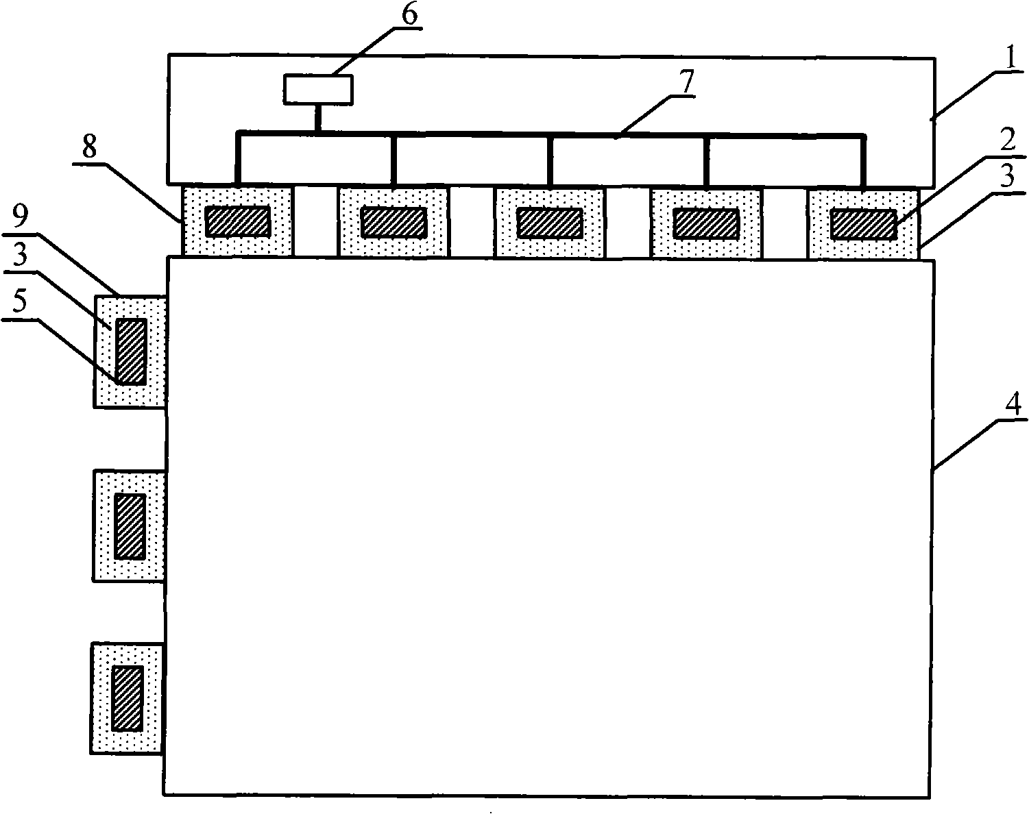
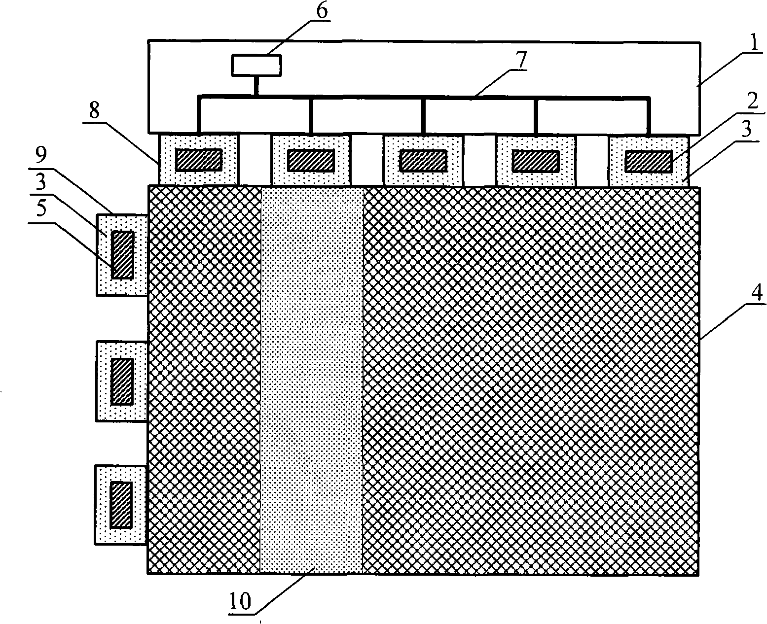
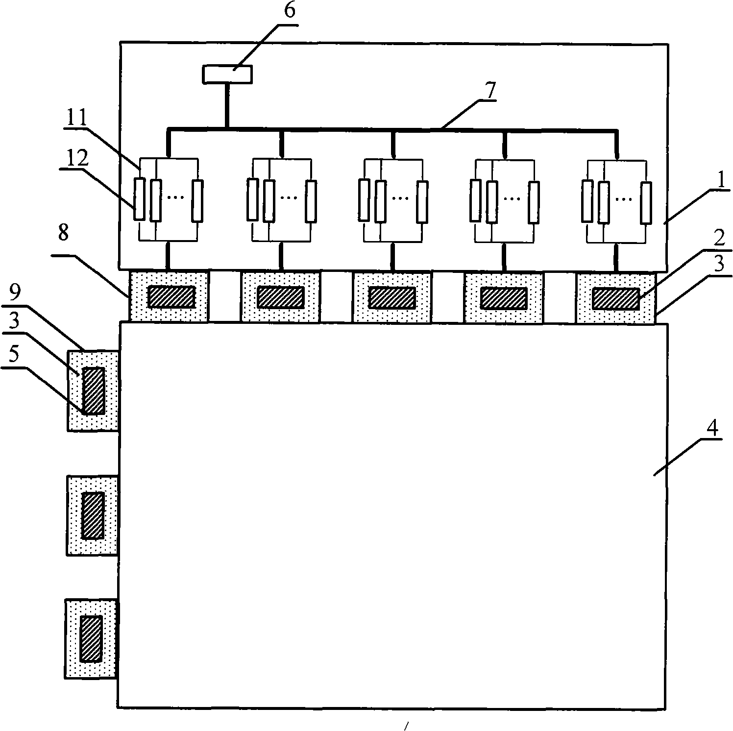
[0028] image 3 A schematic structural diagram of a differential adjustment circuit is shown for the present invention. like image 3 As shown, the display difference adjustment circuit in this embodiment includes: a PCB gamma module 6 and a plurality of data line driving circuits 8 , and the PCB gamma module 6 is connected to each data line driving circuit 8 through a gamma circuit wiring 7 . Each reference voltage signal provided by the PCB gamma module 6 for the data line driving circuit 8 is correspondingly provided ...


PUM


Abstract

The invention relates to a circuit and a method regulating display difference. The circuit for regulating display difference comprises a printed circuit board gamma module and a plurality of driving circuits, wherein the printed circuit board gamma module is connected with each driving circuit through one or more leading wires, and a connecting circuit with an adjustable resistor is in series connected to each leading wire between the printed circuit board gamma module and each driving circuit. The method for regulating display difference comprises the following steps: when the display difference exists in a display area and other display areas on a liquid crystal display panel, and the resistance of the connecting circuit(s) on the leading wire(s) in the display area(s) is regulated. Since the structure of the printed circuit board driven by the liquid crystal display is improved, the invention realizes the purpose of flexibly regulating the display of the corresponding area of a group of the peripheral circuit leading wires on a basal plate, reduces the display difference between the corresponding areas of different groups of the peripheral circuit leading wires and enhances the display uniformity between the corresponding areas of different groups of the peripheral circuit leading wires on the entire basal plate.

Description

technical field [0001] The invention relates to a display difference adjustment circuit and method, and belongs to the field of liquid crystal display. Background technique [0002] figure 1 It is a structural schematic diagram of an existing thin film transistor (Thin Film Transistor, TFT for short) liquid crystal display (Liquid Crystal Display, short for short) driving printed circuit board (Printed Circuit Board, PCB for short) circuit. The TFT LCD driving printed circuit board 1 is an electrical structure for driving the panel, including: a PCB gamma (Gamma) module 6 and a Gamma circuit wiring 7 . The PCB gamma module 6 provides a reference voltage signal converted from digital to analog for the data line (DATA) driving integrated circuit 2 . There can be multiple reference voltage signals, generally 5 to 10. The data line driving circuit 8 includes a flexible film 3 and a data line driving integrated circuit arranged in the flexible film 3 . The gate line (GATE) dr...

Claims


Application Information

Patent Timeline
IPC IPC(8): G02F1/1362G09G3/36
Inventor 彭志龙
Owner K TRONICS (SUZHOU) TECH CO LTD
Why Eureka
Try Eureka