Rotor for a flotation machine, method for forming same, and method for maintenance of same

A flotation machine and rotor technology, used in flotation, chemical instruments and methods, mixers, etc., can solve the problems of difficult and expensive handling, transportation and storage of heavy rotor parts, and reduce the cost of molding tools and molds. Small, easy to transport and store, low cost

Active Publication Date: 2009-09-23
METSO OUTOTEC (FINLAND) OY
View PDF7 Cites 11 Cited by
  • Summary
  • Abstract
  • Description
  • Claims
  • Application Information

AI Technical Summary

Problems solved by technology

The problem with prior art rotors is that in order to repair damage or repairs, the entire rotor must be removed from the flotation cell, even if only a part of it needs to be repaired; and it must be transported to a repair location
Difficult and expensive to handle, transport and store large and heavy rotor components

Method used


Image

  • Rotor for a flotation machine, method for forming same, and method for maintenance of same
  • Rotor for a flotation machine, method for forming same, and method for maintenance of same
  • Rotor for a flotation machine, method for forming same, and method for maintenance of same

Examples


Embodiment Construction

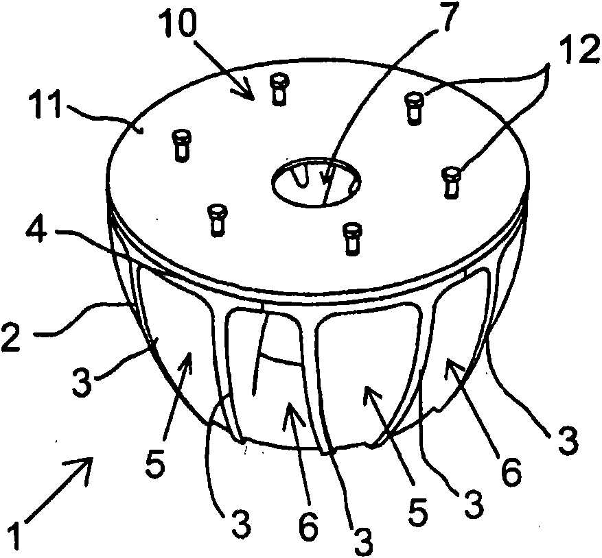
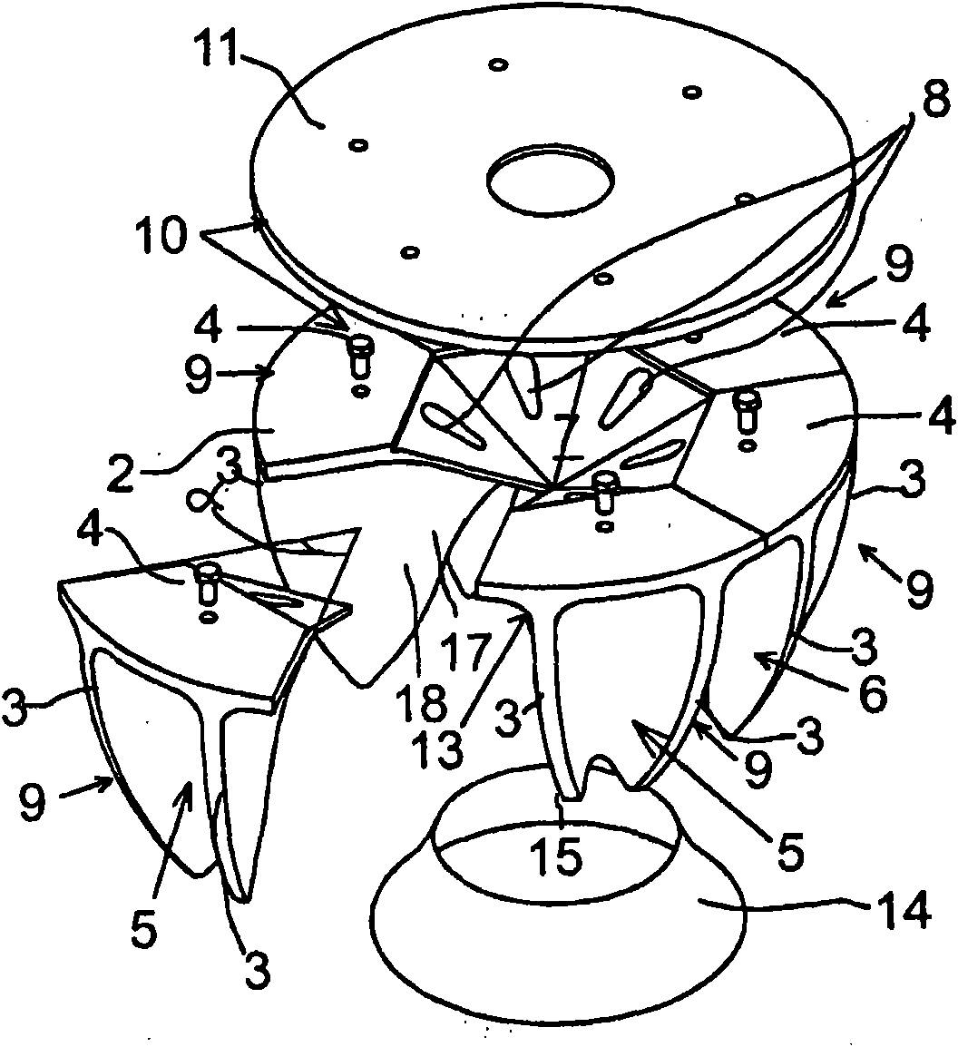
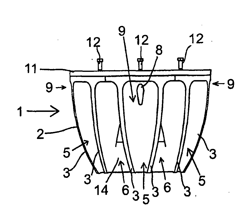
[0041] Figure 1-4 Shown is the rotor of the flotation machine used to disperse air into the sludge mixed with the rotor in the flotation cell (not shown). The rotor is fastened on a shaft (not shown). The rotor includes a cover flange 11 , a modular rotor body 2 and a bottom ring 14 , and the rotating shaft can be fastened on the cover flange 11 .

[0042] The rotor body 2 includes blades 3, in Figure 1-4There are 12 blades in the exemplary embodiment. The blades 3 extend radially outward with respect to the center of the rotor, and the blades 3 taper arcuately towards the lower end. The rotor body 2 also includes an upper wall 4 extending transversely (horizontally) relative to the blades 3 at the upper ends of the blades 3 so that blades adjacent to each other and parts of the upper wall 4 between these blades mutually Alternating radial air ducts 5 and slime ducts 6 are defined therebetween. Furthermore, the inclined portion of the upper wall 4 extending towards the ...


PUM


Abstract

The invention relates to a rotor (1) for a flotation machine for dispersing air into slurry around the rotor, the rotor comprising a body (2) equipped with a set of blades (3). The body (2) is assembled from radial sector modules (9). The rotor comprises fastening means (10) for joining the sector modules (9) to each other. In the method for forming a rotor, radial sector modules (9) are produced, and the rotor body (2) is assembled from a number of sector modules (9). Finally, in the method for maintenance of a rotor, a damaged sector module (9) is detached from the body (2) and replaced by a defect-free sector module.

Description

technical field [0001] The invention relates to a flotation machine rotor as defined in the preamble of claim 1 . The invention also relates to a method as defined in the preamble of claim 21 . Furthermore, the invention relates to a method as defined in the preamble of claim 22 . Background technique [0002] The present invention generally relates to flotation machines for separating valuable components, for example, from mineral-containing sludges in a so-called flotation process. The rotor of the flotation machine, object of the present invention, rotates in the tank containing the slime, or so-called flotation cell, so that the rotor agitates the slime and disperses the air required for froth generation into the slime to form air bubbles. Air is introduced into the rotor via air channels in the rotor shaft. The air bubbles dispersed in the slime rise to the surface of the slime, and the components to be separated adhere to the air bubbles in the froth. The component...

Claims


Application Information

Patent Timeline
Patent Type & Authority Applications(China)
IPC IPC(8): B03D1/14
CPCB01F27/071
Inventor A·林内
Owner METSO OUTOTEC (FINLAND) OY
Why Eureka
Try Eureka