
Control device for power transmission device for vehicle

A technology of power transmission device and control device, applied in the direction of control device, engine control, vehicle components, etc., can solve problems such as poor fuel injection amount

Active Publication Date: 2012-06-20
ISUZU MOTORS LTD
View PDF2 Cites 0 Cited by
  • Summary
  • Abstract
  • Description
  • Claims
  • Application Information

AI Technical Summary

Problems solved by technology

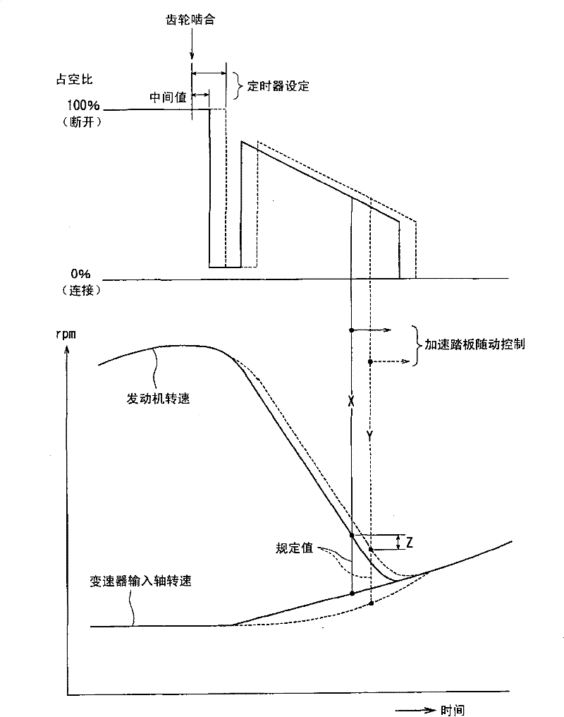
Thus, in Figure 5 In the action during shifting shown in , when the difference between the engine speed and the speed of the transmission input shaft reaches a specified value (B), that is, when the control mode of the engine control device is restored from engine control when shifting to accelerator pedal follow-up During the control, sometimes the difference in the upper limit value of the fuel injection amount exerts an influence and produces a large difference in the fuel injection amount supplied to the engine.

Method used


Image

  • Control device for power transmission device for vehicle
  • Control device for power transmission device for vehicle
  • Control device for power transmission device for vehicle

Examples


Embodiment Construction

[0026] Hereinafter, embodiments of the present invention will be described in detail with reference to the accompanying drawings.

[0027]In the diagram showing the overall structure of the power transmission device of the vehicle and the control device thereof according to the embodiment of the present invention Figure 4 Among them, the power transmission device includes an engine (diesel engine) 1, a fluid coupling 2, a clutch (wet multi-plate clutch) 3, and a transmission 4 connected in the axial direction. The output shaft of the engine 1 is integrally fixed with the pump 21 of the fluid coupling 2 , and the input shaft 32 of the clutch 3 is fixed to the output shaft of the turbine 22 facing the pump 21 . In addition, the output shaft 33 of the clutch 3 is fixed integrally with the input shaft of the transmission 4, and the output shaft 41 of this transmission 4 is connected with the wheel which is not shown in figure.

[0028] The fluid coupling 2 is provided with a lock...


PUM


Abstract

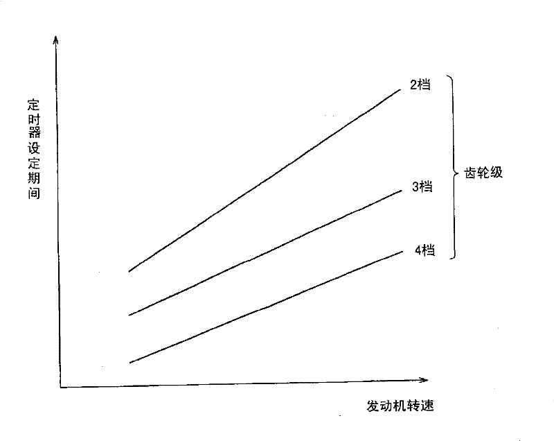
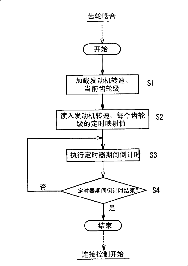
The invention relates to a control device for a power transmission device for a vehicle having a clutch (3) between an engine (1) and a transmission (4), the control device preventing variation in torque of the engine and shift shock when the mode of an engine control returns from engine control for shifting to accelerator pedal following control for normal travel. Timer means (62) is provided ina clutch control device (6) for disengaging the clutch (3) in shift operation and engaging it when the shift is completed. The timer means (62) controls the time point at which control for engaging the clutch is started, and the control is based on conditions etc. of the engine. Because increment conditions of the amount of clutch engagement varies to change conditions of variation of the speed of the engine, conditions of the engine when engine control in shift operation returns from engine control for shift operation to accelerator pedal following control for normal travel can be set to conditions where variation in torque of the engine due to switchover between the control modes does not occur.

Description

technical field [0001] The present invention relates to a control device for a vehicle power transmission device having a clutch between an engine and a transmission, the control device for the vehicle power transmission device having an engine for performing accelerator pedal follow-up control with an accelerator pedal depression amount as a basic parameter A control device and a clutch control device for controlling the connection amount of the clutch. Background technique [0002] As a development trend of vehicles in recent years, for the purpose of easy steering, vehicle power transmission systems that automate shifting operations, clutch operations, and the like have become popular. Among such vehicle power transmission devices, there is a power transmission device in which a diesel engine is mounted, a parallel shaft gear mechanism type transmission is used as a transmission, an automatic clutch is arranged, and a hydraulic force is installed between the engine and th...

Claims


Application Information

Patent Timeline
Patent Type & Authority Patents(China)
IPC IPC(8): B60W10/02F02D29/00B60W10/04F16D48/02B60W10/06
CPCF16D2500/3144F16D2500/7044B60W2540/10F16D2500/3166F16D2500/50684B60W10/06B60W2510/1015B60W10/02F16D2500/70458F16D2500/50287F16D2500/3067F02D29/02F16D48/06B60W2510/0638B60W30/18027
Inventor 岩男信幸薄叶浩志
Owner ISUZU MOTORS LTD
Learn More