Antenna

An antenna and coil conductor technology, which is applied to antennas, helical antennas, antenna parts and other directions, can solve the problems of difficult to achieve miniaturization and high gain of the antenna, and the decrease of gain in the high frequency region, so as to reduce the attenuation loss and improve the gain. Effect

Inactive Publication Date: 2009-09-23
NOF CORP +2
View PDF3 Cites 29 Cited by
  • Summary
  • Abstract
  • Description
  • Claims
  • Application Information

AI Technical Summary

Problems solved by technology

However, when the amount of magnetic powder mixed in is actually increased, problems such as a decrease in the gain in the high-frequency region due to the attenuation loss of the magnetic material occur, and it is difficult to achieve miniaturization and high gain of the antenna.

Method used


Image

  • Antenna
  • Antenna
  • Antenna

Examples


Embodiment 1

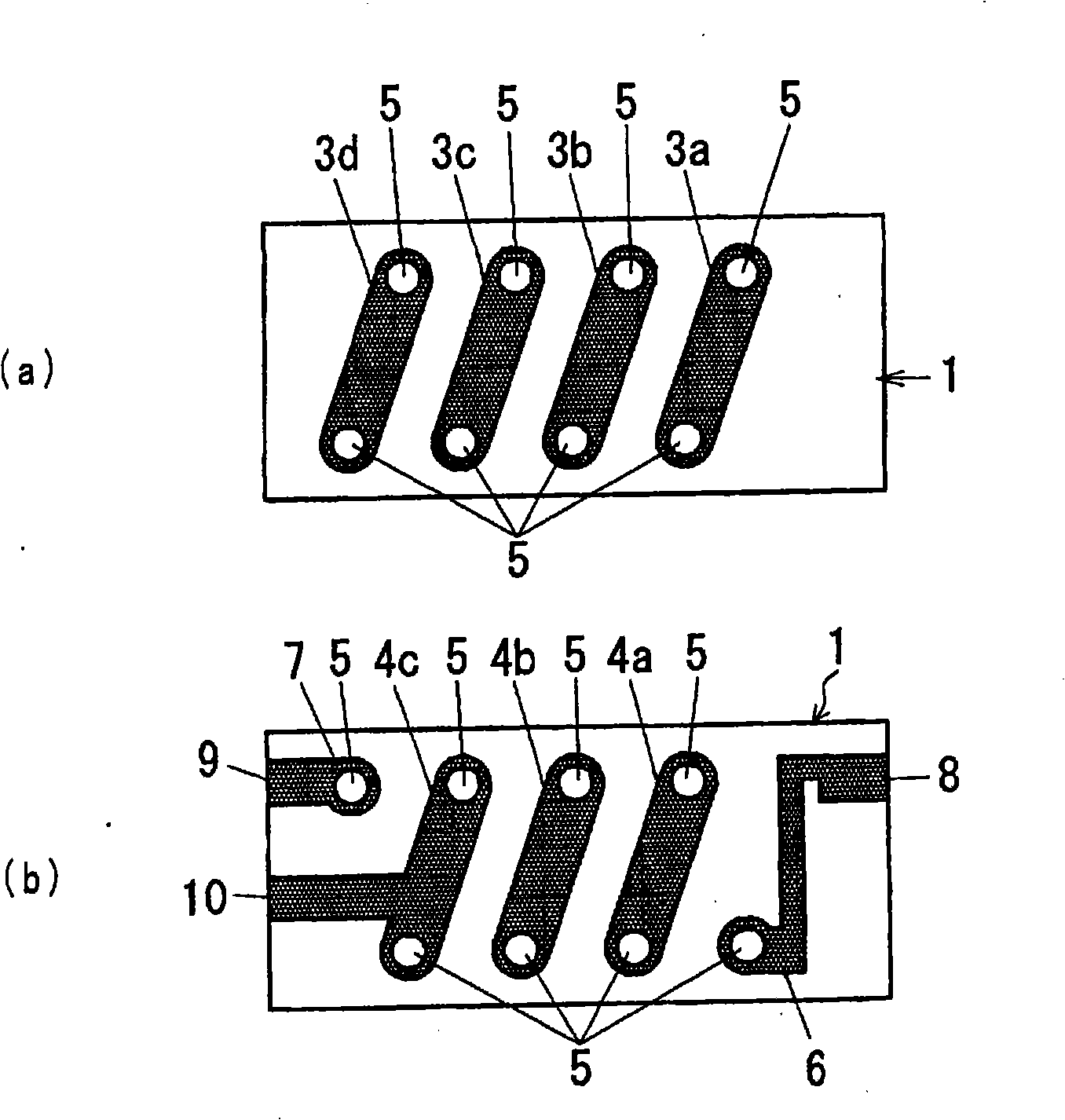
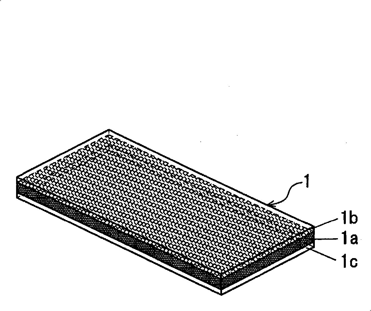
[0032] Figure 1 ~ Figure 3 The antenna structure of Embodiment 1 of the present invention is shown. figure 1 is the stereogram of the antenna, figure 2 is showing figure 1 The surface and back of the figure, figure 2 (a) showing the surface diagram, figure 2 (b) shows the back view. Reference numeral 1 is a magnetic core having a laminated structure formed such that a first resin layer 1a mixed with magnetic powder is provided at the center, and a second resin layer 1b and a third resin layer 1c not mixed with magnetic powder are sandwiched. The structure of the first resin layer 1a is maintained. The details of this magnetic core 1 will be described later.

[0033] Reference numeral 2 is a coil conductor, and constitutes the following conductor pattern. On the surface of the magnetic core 1, four conductor patterns 3a to 3d are formed as first conductor patterns. Each of the conductor patterns 3a to 3d is not parallel to the left and right sides of the magnetic co...

Embodiment 2

[0048] Next, Embodiment 2 of the antenna of the present invention will be described.

[0049] Figure 7 The structure of the magnetic core used in the antenna of Example 2 of the present invention is shown.

[0050] Figure 7 The illustrated magnetic core 1A has a constant thickness as a whole, but the thicknesses of the first, second, and third resin layers 1d, 1e, and 1f vary linearly. Specifically, the first resin layer 1d is set to be thin on the right end side of the magnetic core 1A, and the thicknesses of the second resin layer 1e and the third resin layer 1f are set to be thick. The thickness of the first resin layer 1d is set thicker on the left end side of the magnetic core 1A, and the thicknesses of the second resin layer 1e and the third resin layer 1f are set thinner. The thickness gradually changes from the right end side to the left end side of the core 1A in a linear form.

Embodiment 3

[0052] Next, Embodiment 3 of the antenna of the present invention will be described.

[0053] Figure 8 The structure of the magnetic core used in the antenna of Embodiment 3 of the present invention is shown.

[0054] Figure 8 The left half of the illustrated magnetic core 1B is a first core part 11 of a single-layer structure composed only of a resin layer 1g mixed with magnetic powder, and the right half is a second core part 12 of a laminated structure. The second magnetic core part 12 is formed of the following resin layers: a first resin layer 1h in which a resin layer mixed with magnetic powder is formed in the center of the right half; The second resin layer 1i formed of only resin and the third resin layer 1j formed of only resin.


PUM


Abstract

An antenna that while maintaining a desirable level of gain for radio waves of a wide range of frequencies, realizes a compact outline, constructed of a core (1) of laminate structure. The core is in the form of a plate with rectangular contour and comprised of a third resin layer (1c) and second resin layer (1b) consisting only of a resin not containing any magnetic powder and, interposed therebetween, a first resin layer (1a) containing a magnetic powder as a central layer, the first, second and third resin layers constituting a laminate structure. Preferably, in the core (1) of laminate structure, a polymer resin is used in each of the resin layers and a soft ferrite powder is used as the magnetic powder.

Description

technical field [0001] The present invention relates to a structure of a small antenna, and relates to a high-gain antenna of a size that can be built in a portable terminal device or the like. Background technique [0002] In portable terminal equipment in recent years, there have been antennas such as FM radio broadcasting and TV broadcasting from the VHF band to the UHF band, or portable wireless communications in the high frequency band of the UHF band, etc. Receive radio waves in a wide range of frequencies. When receiving radio waves with a wide frequency range, it is of course necessary to have an antenna with a wide frequency bandwidth corresponding to each signal frequency. However, the wavelength of radio waves in the UHF band is several tens of centimeters, and the wavelength of radio waves in the VHF band is several meters. Therefore, an antenna that can support both UHF and VHF bands with a single body is manufactured and built in a volume. In the case of limi...

Claims


Application Information

Patent Timeline
Patent Type & Authority Applications(China)
IPC IPC(8): H01Q7/08H01Q1/38
CPCH01Q1/362H01Q7/06H01Q1/38H01Q7/08H01Q11/08
Inventor 园田贤作菅力也城田健一小池清
Owner NOF CORP
Why Eureka
Try Eureka