
Brake cooling water monitoring device for automobile

A monitoring device and automobile braking technology, applied in the direction of braking safety system, etc., can solve problems such as inability to take preventive measures, failure to take emergency braking measures, major traffic accidents, etc., and achieve the effect of preventing major traffic accidents

Inactive Publication Date: 2009-09-30
郑昌茂
View PDF3 Cites 1 Cited by
  • Summary
  • Abstract
  • Description
  • Claims
  • Application Information

AI Technical Summary

Problems solved by technology

However, since the vast majority of trucks are not equipped with a brake cooling water monitoring device at present, once the water spray device is blocked or lacks water, it may cause a major traffic accident; in order to be able to monitor the braking system at any time, the application No. "01226211.0", the name is "automobile brake system cooler device", the application number is "200810045952.X", the name is "brake hub cooler", and the application number is "200410012719.3", the name is " The invention patents of "method and device for fault detection of motor vehicle braking system" all disclose technical solutions for using temperature sensors to monitor the temperature of brake pads, but none of these technical solutions can prevent problems before they happen
This is because when the temperature of the brake pads and the brake hub rises, if the water spray device is blocked or lacks water, etc., emergency braking measures cannot be taken.

Method used


Image

  • Brake cooling water monitoring device for automobile
  • Brake cooling water monitoring device for automobile

Examples


Embodiment Construction

[0010] The present invention will be further described below in conjunction with accompanying drawing and specific embodiment:

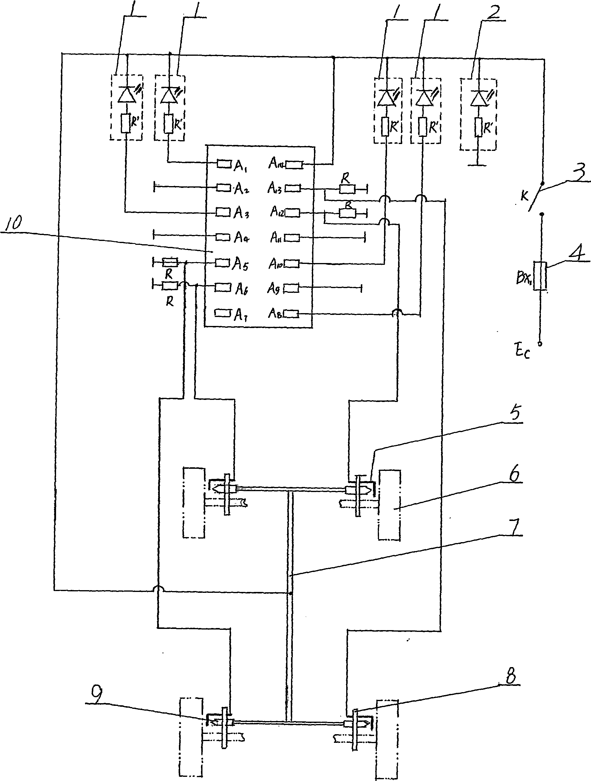
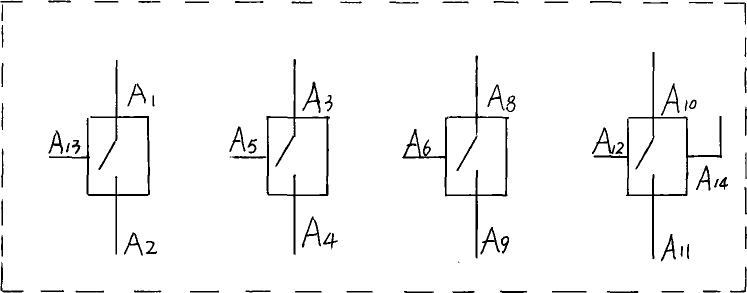
[0011] exist Figure 1~2 Among them, the four nozzles 9 are respectively fixed at positions close to the four brake hubs 6 through brackets 8, and each nozzle 9 communicates with each other through the cooling water pipe 7 fixed on the chassis of the automobile; a conductive probe 5 is fixed on each bracket 8 , the front end of the conductive probe is close to the water spout of the nozzle 9 and maintains a small gap with the water spout. The four-way analog switch integrated circuit module 10 whose model is IC4066 is provided with four internal control switches, and the control terminal A of each internal control switch is 6 feet, A 12 feet, A 5 feet, A 13 The pins are respectively connected with the conductive probes 5 fixed on the left front wheel brake hub, the right front wheel brake hub, the left rear wheel brake hub and the right rear whee...


PUM


Abstract

The invention discloses a brake cooling water monitoring device for an automobile, belongs to a brake safety monitoring device, and aims to provide a device capable of monitoring a brake water spray system in real time. The device comprises nozzles arranged on brake hubs, a cooling water pipe communicating the nozzles, and conductive probes (5) arranged on the nozzles (9); four control ends of a quad bilateral switch integrated circuit module (10) are electrically connected with the conductive probes (5) corresponding to the four control ends respectively; each control end correspondingly controls an internal control switch; a positive terminal of each internal control switch is respectively connected in parallel with an anode of a power supply through a monitoring pilot light (1), while a negative terminal is respectively connected in parallel with a cathode of the power supply through a bias resistor R; and the nozzles (9) are electrically connected with the anode of the power supply through conducting wires. The monitoring device has the advantages of simple structure, convenient use, low cost, high reliability and the like, and can be used for various autotrucks.

Description

Technical field: [0001] The invention relates to a safety monitoring device for automobile brakes, in particular to a device for monitoring cooling water of automobile brakes. Background technique: [0002] As we all know, whether the brake device can work normally is the key to ensuring driving safety. During the braking process of the truck, the brake pads will rub against the brake hub violently and generate high temperature, which will cause the brake pads to wear out rapidly and the brake hub to burn red, resulting in brake failure; especially for large-tonnage trucks when they go downhill for a long distance During the continuous braking process, the above phenomenon is more serious. In order to avoid brake pads and brake hubs from overheating and causing brake failure, the usual measure is to install a water spray device near the brake hub to cool down the brake pads. However, since the vast majority of trucks are not equipped with a brake cooling water monitoring d...

Claims


Application Information

Patent Timeline
Patent Type & Authority Applications(China)
IPC IPC(8): B60T17/22
Inventor 郑昌茂
Owner 郑昌茂
Learn More