
Ground hydraulic augmented injection pump

A hydraulic and ground technology, used in pumps, piston pumps, liquid variable capacity machines, etc., can solve the problems affecting the service life of the booster pump, the inability to fine-tune the water pressure, and the troublesome replacement of the water distributor. The effect of reducing water impurities and prolonging life

Active Publication Date: 2012-05-23
ZHONGCHAO LIANHE ENERGY SCI & TECH BEIJING CO LTD
View PDF5 Cites 0 Cited by
  • Summary
  • Abstract
  • Description
  • Claims
  • Application Information

AI Technical Summary

Problems solved by technology

[0004] (1) Since the ground double-pressure hydraulic booster pump does not process the high-pressure flowing water from the pump station before booster injection, the impurities in the incoming water will affect the service life of the booster pump and reduce the pump efficiency;
[0005] (2) This kind of surface dual-pressure hydraulic injection pump also needs to be used in conjunction with the water distributor placed in the well, and it is troublesome to replace the water distributor placed in the well;
[0007] (4) The liquid inlet valve and liquid discharge valve of the booster cylinder are set in a separate delivery pipeline, which is easily damaged in the open air
[0008] (5) This kind of surface dual-pressure hydraulic booster injection pump cannot fine-tune the incoming water pressure. When the pump efficiency decreases or the pressure of the water injection well increases, another booster injection pump must be replaced

Method used


Image

  • Ground hydraulic augmented injection pump
  • Ground hydraulic augmented injection pump
  • Ground hydraulic augmented injection pump

Examples


Embodiment 1

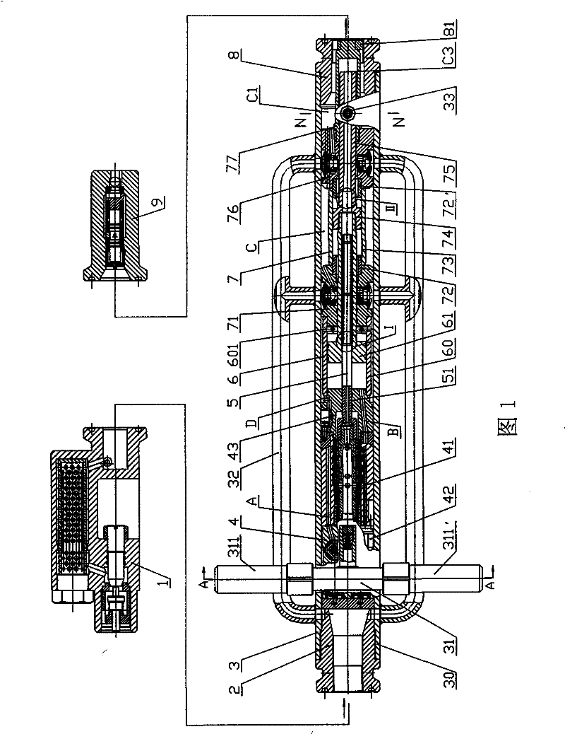
[0125] Such as figure 1 As shown, the ground hydraulic injection pump is mainly composed of an inlet filter decompression device 1, a water inlet joint of the pump station pipe network (left joint for short) 2, a pump main body 3, a boost outlet joint 8 (right joint for short) and a boost outlet The water distribution joint 9 is formed; the pump main body 3 includes a housing main body 30 and a reversing valve 4, a reversing control device 5, a power cylinder 6 and a booster that are arranged in the housing main body 30 and arranged sequentially and coaxially along the axis of the housing main body 30. Pressure cylinder 7; the right end of the inlet filter decompression device 1 is connected with the left joint 2 with a clamp (not shown in the figure), and the right end of the left joint 2 is threaded and sealed with the housing main body 30; the left end of the right joint 8 is connected with the housing The main body 30 is threaded and sealed, and the right end of the right ...

Embodiment 2

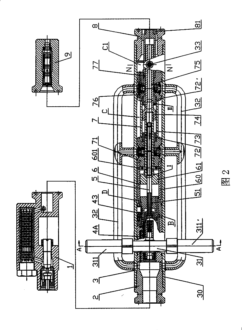
[0140] Such as figure 2 , Figure 18 and Figure 20 As shown, the surface injection pump of this embodiment is mainly composed of an inlet filter decompression device 1, a pump station pipe network water inlet joint (left joint for short) 2, a pump main body 3, a pressurized outlet joint 8 (right joint for short) and a booster The pressure outlet water distribution joint 9 is formed; the pump main body 3 includes a housing main body 30 and a reversing valve 4A, a reversing control device 5, a power cylinder 6 and a booster that are arranged in the housing main body 30 and arranged in sequence along its axis and coaxially. Pressure cylinder 7; the right end of the inlet filter decompression device 1 is connected with the left joint 2 with a clamp (not shown in the figure), and the right end of the left joint 2 is threaded and sealed with the housing main body 30; the right joint 8 is connected with the housing main body 30 is threaded and sealed, the right end of the right j...

Embodiment 3

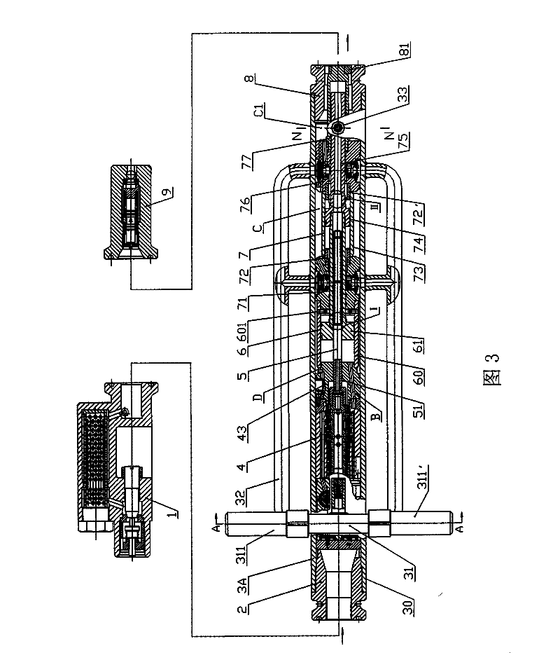
[0144] Such as image 3 As shown, the ground injection pump of this embodiment is mainly composed of an inlet filter decompression device 1, a water inlet joint of the pump station pipe network (abbreviated as the left joint) 2, a pump main body 3A, a pressurized outlet joint 8 (abbreviated as the right joint) and an increaser The pressure outlet water distribution joint 9 is formed; the pump main body 3A includes a housing main body 30 and a reversing valve 4, a reversing control device 5, a power cylinder 6 and a booster that are arranged in the housing main body 30 and arranged in sequence along its axis and coaxially. Pressure cylinder 7; the right end of the inlet filter decompression device 1 is connected with the left joint 2 with a clamp (not shown in the figure), and the right end of the left joint 2 is threaded and sealed with the housing main body 30; the right joint 8 is connected with the housing main body 30 is threaded and sealed, the right end of the right join...


PUM


Abstract

The invention provides a ground hydraulic augmented injection pump, which is used for oilfield underground water injection. The pump comprises an inlet-filtering pressure-reducing device, a liquid inlet joint, a pressure-increasing liquid outlet joint, a pump body and a pressure-increasing outlet water-distribution joint, wherein the inlet-filtering pressure-reducing device is provided with a filter and a pressure-reducing valve with a check valve; the liquid inlet joint is connected with a water outlet of the inlet-filtering pressure-reducing device; the pump body comprises a shell body, a liquid supply pipeline, reversing valves which are sequentially and coaxially arranged in the shell body along the axis of the shell body, a power cylinder, a reversing control device and a pressure-increasing cylinder; one end of the shell body is connected with the liquid inlet joint, and the other end of the shell body is connected with the pressure-increasing liquid outlet joint; the liquid supply pipeline is connected with the pressure-increasing cylinder; each reversing valve is provided with a first channel, a second channel and a plurality of ports; the first channel and the second channel are communicated with a right cylinder body and a left cylinder body of the power cylinder respectively; and the pressure-increasing outlet water-distribution joint connected with the pressure-increasing liquid outlet joint is provided with a water distributor with the check valve. The ground hydraulic augmented injection pump has the advantages of capability of meeting the requirements of various water injection wells on water injection, long life span, high efficiency and energy conservation.

Description

technical field [0001] The invention relates to a special water injection pump for oil fields, in particular to using the incoming water from the pipe network of the pumping station as power to finally increase or decrease the pressure of the incoming water; Or the oil pump is used as power to drive the power cylinder to finally increase the pressure of the incoming water. Background technique [0002] At present, oilfield water injection in the world basically uses a single pump pressure to inject water into multiple wells. Therefore, there are generally under-injection wells that need to be boosted and low-pressure water injection wells that need to be adjusted. Distinguishing different well conditions A new type of injection booster pump powered by incoming water, rather than simply relying on pressure reducing valves and electric booster injection pumps to achieve single-well partial pressure water injection is to solve under-injection of water injection wells in oil fie...

Claims


Application Information

Patent Timeline
Patent Type & Authority Patents(China)
IPC IPC(8): F04B9/10E21B43/00
Inventor 李洪敏
Owner ZHONGCHAO LIANHE ENERGY SCI & TECH BEIJING CO LTD
Learn More