Supercharge Your Innovation With Domain-Expert AI Agents!

Inspection jig

A technology for testing fixtures and rods, applied in measuring devices, instruments, measuring electricity, etc., to achieve the effect of easy conductor resistance

Active Publication Date: 2012-03-21
NEC PLATFORMS LTD
View PDF6 Cites 0 Cited by
  • Summary
  • Abstract
  • Description
  • Claims
  • Application Information

AI Technical Summary

Problems solved by technology

This is because these conventional techniques do not address the inherent problems of such inspection fixtures

Method used


Image

  • Inspection jig
  • Inspection jig
  • Inspection jig

Examples


Embodiment Construction

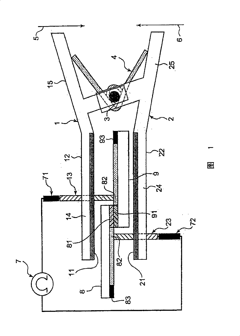
[0015] refer to figure 1 , an inspection jig according to a first exemplary embodiment of the present invention will be described.

[0016] figure 1 The test fixture shown is designed to measure the electrical resistance between two objects 8 and 9 to be measured. The inspection jig includes a pair of insulating rods 1 and 2 which are rotatably connected to each other by a shaft 3 . One side of the rods 1 and 2 seen from the shaft 3 is called the working part 14 and 24 , and the other side of the rods 1 and 2 seen from the shaft 3 is called the manipulation part 15 and 25 .

[0017] The working parts 14 and 24 respectively have inwardly facing surfaces 11 and 21 facing each other and outwardly facing surfaces 12 and 22 facing away from each other. Spring 4 is arranged between rods 1 and 2 . The spring 4 is engaged with the manipulating parts 15 and 25 to bias the manipulating parts 15 and 25 in a direction such that the inner surfaces 11 and 21 are brought closer to each o...


PUM


Abstract

The invention relates to an inspection jig. In an inspection jig for measuring resistance between the objects to be measured, a pair of opposite rods are disposed face to face, with interval provided therebetween, and the opposite rods are designed to be capable of approaching to and depart from each other. A pair of contacts are disposed at positions not facing each other on the rods. The rod isbias pressed in contact with the object to be measured.

Description

technical field [0001] The present invention relates to a test fixture for measuring electrical resistance between objects to be measured. Background technique [0002] Japanese Laid-Open Patent Publication No. H08-304485 (Patent Document 1) discloses an electric device having a function of diagnosing insulation between two electrodes provided in an object to be measured. The electric device has two bolts that are in contact with two electrodes of an object to be measured to diagnose insulation between the electrodes. [0003] Japanese Laid-Open Utility Model Publication No. H05-41067 (Patent Document 2) discloses an IC clip for connecting a measuring device or the like to lead terminals of an integrated circuit. The IC clip has pins provided at the ends of a pair of rotatable levers to face each other, the levers being biased by a spring so that the pins approach each other. The pins are pressed onto lead terminals of the integrated circuit by means of springs to establis...

Claims


Application Information

Patent Timeline
Patent Type & Authority Patents(China)
IPC IPC(8): G01R15/00G01R27/02
CPCG01R1/073G01R27/02G01R31/2879G01R31/2884G01R31/2886G01R31/2893
Inventor 山下俊一
Owner NEC PLATFORMS LTD
Features
  • R&D
  • Intellectual Property
  • Life Sciences
  • Materials
  • Tech Scout
  • Unparalleled Data Quality
  • Higher Quality Content
  • 60% Fewer Hallucinations
Learn More