
Pick-up device

A technology of camera device and camera department, which is applied in the direction of image communication, TV, color TV parts, etc. It can solve the problems of easy hand shake, etc., and achieve the effect of improving photographic sensitivity, reducing data volume, and suppressing image blur

Active Publication Date: 2009-09-30
OLYMPUS CORP
View PDF1 Cites 41 Cited by
  • Summary
  • Abstract
  • Description
  • Claims
  • Application Information

AI Technical Summary

Problems solved by technology

[0004] However, as mentioned above, when taking pictures while moving the main body of the device, there is a problem that hand shake is likely to occur.

Method used


Image

  • Pick-up device
  • Pick-up device
  • Pick-up device

Examples


Embodiment approach

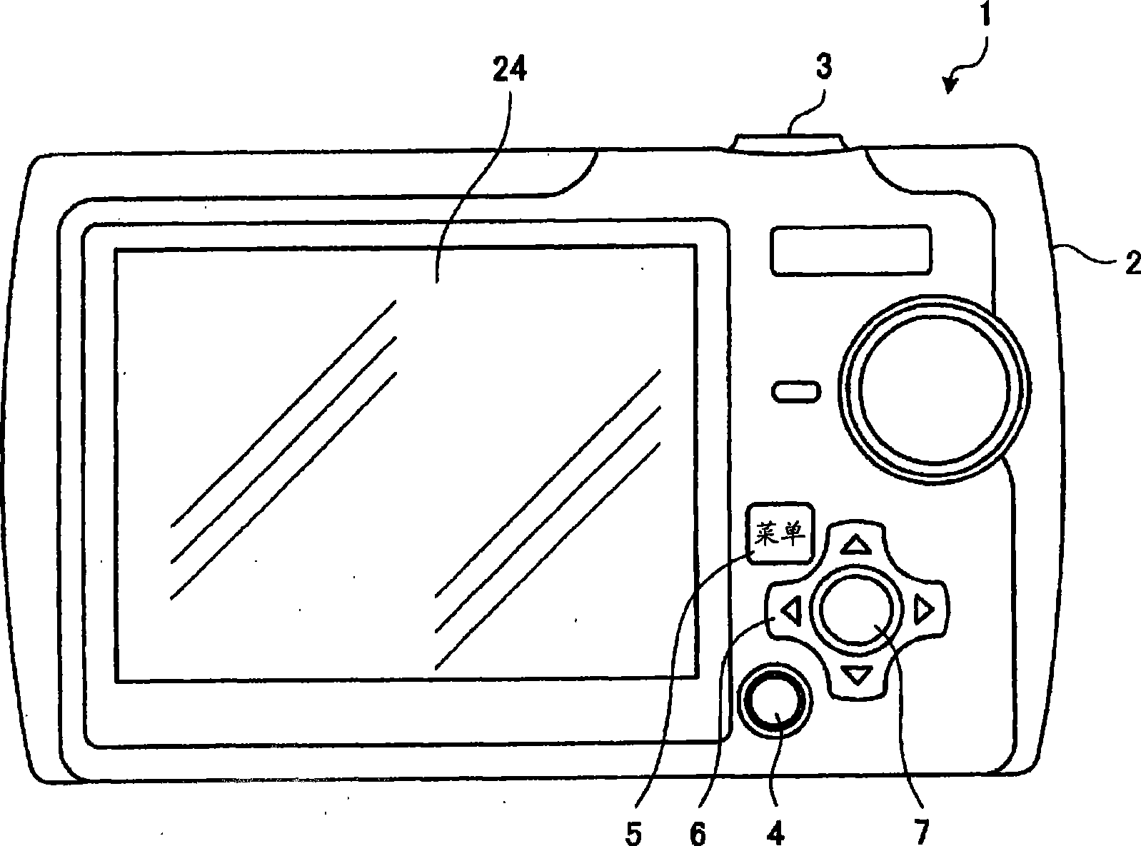
[0035] figure 1 It is a rear view of digital camera 1. Such as figure 1 As shown, a digital camera 1 has a shutter button (shutter release button) 3 provided on the upper surface of the camera body 2 for instructing shooting timing, a power button 4 and a menu button 5 provided on the back of the camera body 2, and has up, down, left, and right buttons. Buttons for each direction (up button, down button, left button, and right button), cross button 6, OK button 7 for confirming operation content, etc., display unit 24 for displaying various screens, and the like. In addition, although not shown, a viewfinder, an imaging lens, and the like are provided on the front surface of the camera body 2 .

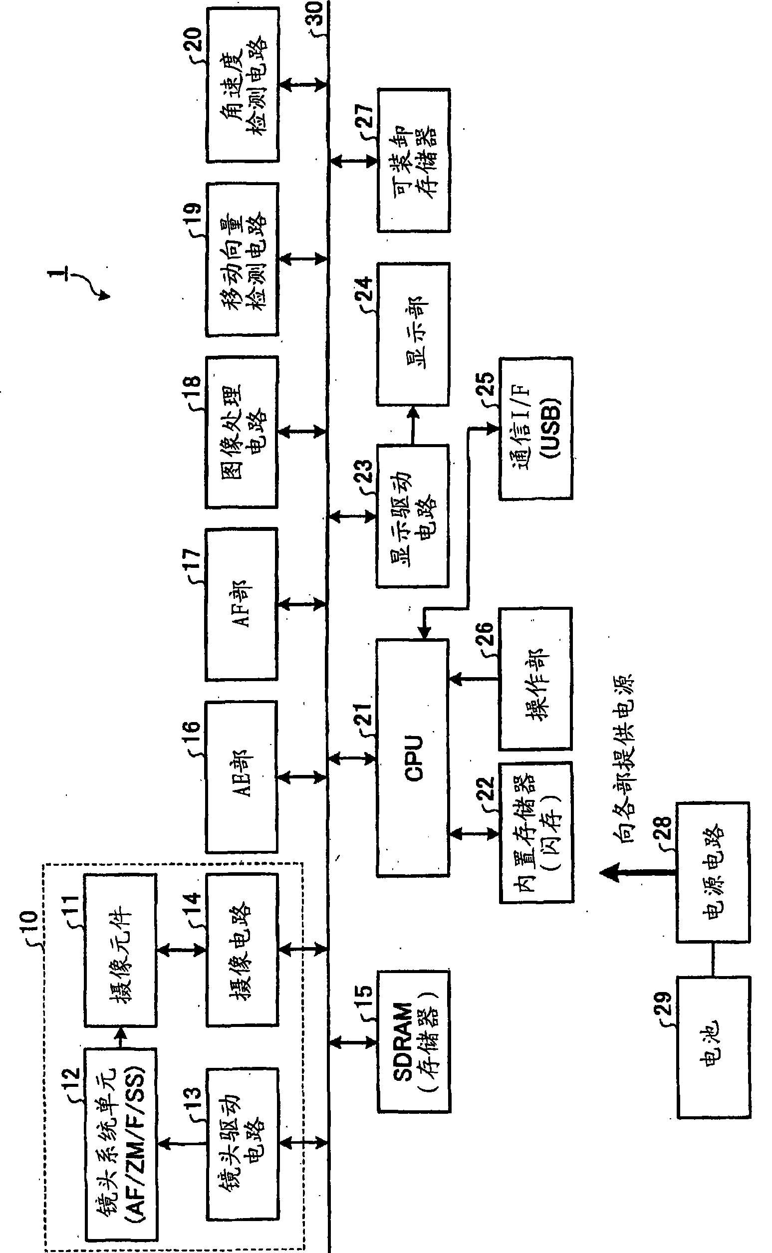
[0036] figure 2 is a block diagram showing the system configuration of the digital camera 1 . Such as figure 2As shown, the digital camera 1 has: an imaging element 11, a lens system unit 12, a lens driving circuit 13, an imaging circuit 14, an SDRAM 15, an AE section 16, an AF...


PUM


Abstract

The present invention provides a pick-up device capable of restraining image blurring caused by hand shake in pick-up processing in moving process. In panorama mode, a CPU 21 calculates lightness of an object representing lightness of the object, sets allowed moving speed determined by setting state of the device. Then, the CPU 21 sets pixel addition according to combination of object lightness and the allowed moving speed, and sets shutter speed (ss), aperture value and ISO photosensibility as exposure condition in pick-up processing. Then in the pick-up processing, the CPU 21 executes pixel addition drive for a pick-up section according to set of the pixel addition, and controls exposure of the pick-up section according to set of the exposure condition.

Description

technical field [0001] The present invention relates to an imaging device having an imaging unit having a plurality of pixels for receiving and photoelectrically converting an image of a subject, and continuously taking pictures while changing a relative position to the subject processed to generate a plurality of photographic image data. Background technique [0002] Conventionally, imaging devices such as digital cameras are known to have a panorama shooting mode in which a plurality of consecutive captured images are synthesized to generate a panoramic image. In this panorama photography mode, a subject is photographed for each part while moving the imaging device, whereby a panoramic image in which photographed images of the respective parts are connected can be obtained. Here, in order to obtain a panoramic image, it is necessary to perform photography so that a part of the connected photographed images overlap each other, and as a technique for realizing this, there i...

Claims


Application Information

Patent Timeline
Patent Type & Authority Applications(China)
IPC IPC(8): H04N5/235H04N5/232H04N5/225
Inventor 上村达之
Owner OLYMPUS CORP
Learn More