Supercharge Your Innovation With Domain-Expert AI Agents!

Spray nozzle manifold and process for quenching a hot gas using such an arrangement

一种高温气体、喷嘴的技术,应用在高温气体骤冷领域,能够解决喷雾嘴堵塞等问题

Active Publication Date: 2009-09-30
AIR PROD & CHEM INC
View PDF4 Cites 7 Cited by
  • Summary
  • Abstract
  • Description
  • Claims
  • Application Information

AI Technical Summary

Problems solved by technology

For example, if the nozzle manifold of DE-A-102005004341 is used, severe clogging of the spray nozzles will occur due to the presence of non-gaseous components in the high temperature synthesis gas

Method used


Image

  • Spray nozzle manifold and process for quenching a hot gas using such an arrangement
  • Spray nozzle manifold and process for quenching a hot gas using such an arrangement
  • Spray nozzle manifold and process for quenching a hot gas using such an arrangement

Examples


Embodiment Construction

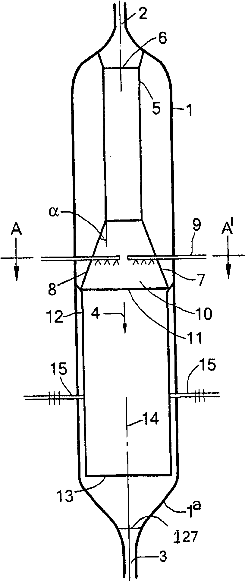
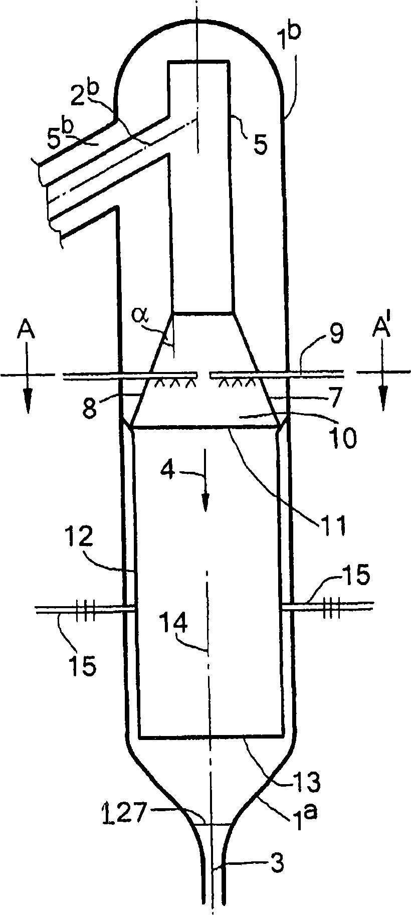
[0012] Define nozzle manifolds using terms such as upper, top, lower, down, horizontal, vertical. These terms refer to nozzle manifolds in such Figure 1-4 Preferred orientation for use shown. These terms are not used to limit the scope of the invention to nozzle manifolds having only this orientation.

[0013] The nozzle manifold according to the invention has a first coaxial channel for supplying atomizing gas and a second coaxial channel present in said first channel for supplying liquid. These channels are preferably tubular. Transversely spaced nozzles are positioned to atomize and eject the liquid in a direction away from the longitudinal axis of the manifold. Preferably, the nozzles are positioned on a line parallel to the longitudinal axis. Preferably, the nozzles are positioned to spray in the same direction perpendicular to the longitudinal axis, spaced apart from additional nozzles positioned at the end of the channel, which may spray in a different direction, a...


PUM


Abstract

Spray nozzle manifold (25) comprising a first co-axial passage (26) for supply of an atomisation gas, a second coaxial passage (27) present in said first passage for supply of a liquid, more than one laterally spaced nozzles (16) for atomisation and spraying liquid in a direction away from the longitudinal axis of the manifold (25) the nozzle is attached to the first passage, said nozzles having an inlet for liquid fluidly connected to said second passage (27), an inlet for atomisation gas fluidly connected to the first passage (26), a mixing chamber (37) wherein atomisation gas and liquid mix and an outlet (24) for a mixture of atomisation gas and liquid, wherein the nozzle has an opening (33) for discharge of atomisation gas which opening is in fluid communication with the first passage at a position upstream of the mixing chamber (37) and wherein a shield (32) is fixed to the first passage (26) surrounding the nozzle.

Description

technical field [0001] The present invention relates to nozzle manifolds, arrangements of such nozzle manifolds and methods of quenching high temperature gases using such arrangements. Background technique [0002] US-A-2006 / 0260191 describes a converter in which the high temperature synthesis gas produced in an adjacent gasification reactor is cooled by injecting a quench liquid into the high temperature synthesis gas flow. In particular, the patent document's Figure 4 A gasification reactor is shown for gasifying solid carbonaceous feedstock to obtain a synthesis gas mixture at a temperature of 1200°C - 1800°C. The reactor has a high temperature synthesis gas outlet at its upper end and a slag outlet at its lower end. The reactor itself is provided with quenching means in order to reduce the temperature in the first step to a temperature below the freezing point of the non-gaseous components present in the synthesis gas. The temperature of the synthesis gas is further r...

Claims


Application Information

Patent Timeline
Patent Type & Authority Applications(China)
IPC IPC(8): B01D47/06B05B7/04B05B15/02B05B15/04F28C3/08B05B12/18B05B12/36B05B15/55
CPCY02E20/18B05B15/0431B05B15/0443B05B7/0475F28C3/08B05B15/025B05B7/0466B05B12/18B05B15/55B05B12/36B01D47/06B05B7/04
Inventor R·范德伯格W·K·哈特维尔德H·J·海嫩T·P·冯科萨克-格洛切夫斯基
Owner AIR PROD & CHEM INC
Features
  • R&D
  • Intellectual Property
  • Life Sciences
  • Materials
  • Tech Scout
  • Unparalleled Data Quality
  • Higher Quality Content
  • 60% Fewer Hallucinations
Learn More