Automatic traction method and apparatus of a continous controllable train

A technology of trains and train status, applied in the field of rail transit, can solve the problems of huge manpower and material resources, no breakthrough in automatic driving technology, failure to effectively realize automatic traction calculation, etc., and achieve the effect of solving continuity problems

Active Publication Date: 2009-10-07
CHINA ACADEMY OF RAILWAY SCI CORP LTD +1
View PDF0 Cites 7 Cited by
  • Summary
  • Abstract
  • Description
  • Claims
  • Application Information

AI Technical Summary

Problems solved by technology

[0004] Due to the failure to effectively realize the automatic traction calculation, my country needs to spend huge manpower and material resources on related work every year, and at the same time, the automatic driving technology that has important application prospects on high-speed railways has not be

Method used


Image

  • Automatic traction method and apparatus of a continous controllable train
  • Automatic traction method and apparatus of a continous controllable train
  • Automatic traction method and apparatus of a continous controllable train

Examples


Embodiment 1

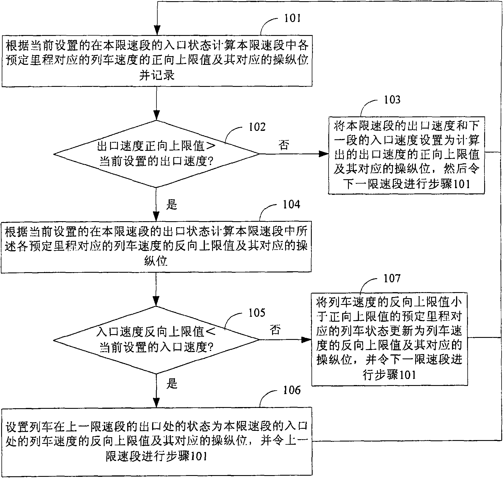
[0036] The automatic traction method of the train in the present embodiment needs to set the initial value of the entrance state and the initial value of the exit state of the train in each speed-limited section according to the speed limit of each speed-limited section, and the train state includes the train corresponding to the mileage Speed ​​and control position, when setting the initial value of the entrance state and the initial value of the exit state of the train in each speed-limited section, the speed takes the smaller value among the speed limits of the two adjacent speed-limited sections corresponding to the mileage, and the control position takes is zero, the method is as figure 1 shown, including:

[0037] Step 101, calculate the positive upper limit value of the train speed corresponding to each predetermined mileage in this speed limit segment and its corresponding control position according to the currently set entry state in this speed limit segment, and calc...

Embodiment 2

[0075] The automatic traction device of the train in this embodiment, such as Figure 4 , including a storage module 301, a forward calculation module 302, a first judgment module 303, a reverse calculation module 304, and a second judgment module 305, wherein:

[0076] The storage module 301 saves the basic parameters of the train, the train control requirements, the standard train control curve, the line parameters and the speed limit of the train in each speed limit section, and is used to save the train status of each predetermined mileage, and at the entrance of each speed limit section The initial value of the train state at the entrance and exit is set according to the speed limit of each speed limit section, the predetermined mileage includes the entrance and exit of each speed limit section, and the train state includes the train speed and control position corresponding to the mileage;

[0077] The forward calculation module 302 is used to calculate the positive upper...


PUM


Abstract

The present invention discloses automatic traction method and apparatus of a continous controllable train, and in the technical project provided, if the outlet velocity obtained by forward calculation that according to entry state of the train in the speed limiting segment is bigger than setting value then proceeds reverse calculation to determine what kind of entry state is needed to implement the setting value of the outlet state, and if the entry state of the segment can not satisfy the setting value of the outlet state then renews the outlet state of the prior speed limiting segment and proceeds reverse calculation until the speed limiting segment capable of implementing the outlet state. It is obvious that, in the embodiment of the invention, implementing speed limiting constraint normalized by feedback of the entry state and resolving continuity problem of traction calculation, providing rapid and effective means for route, power supply, trains, operation scheme, design and study of operation chart, and creating condition for further automatic drive study, possessing important engineering significance.

Description

technical field [0001] The invention relates to the technical field of rail transit, in particular to an automatic traction method and device for a continuously controllable train. Background technique [0002] Modern railways take dispatching and command as the core, and are supported by rolling stock, lines, power supply, signals, stations, information and other systems to serve the society. [0003] As the comprehensive embodiment of railway facility capabilities and the link of system comprehensive configuration, traction calculation plays an important role in railway system design, transportation dispatching and commanding, and train manipulation guidance. [0004] Due to the failure to effectively realize the automatic traction calculation, our country needs to spend huge manpower and material resources on related work every year. At the same time, the automatic driving technology that has important application prospects on high-speed railways has not been broken throu...

Claims


Application Information

Patent Timeline
IPC IPC(8): B61L27/04
Inventor 康熊曾宇清于卫东扈海军
Owner CHINA ACADEMY OF RAILWAY SCI CORP LTD
Why Eureka
Try Eureka