Split fume exhauster

A separate structure, oil fume exhaust technology, used in the removal of oil fume, household heating, lighting and heating equipment, etc. Easy and fast installation, the effect of eliminating dirt

Inactive Publication Date: 2010-08-25
王君
View PDF0 Cites 0 Cited by
  • Summary
  • Abstract
  • Description
  • Claims
  • Application Information

AI Technical Summary

Problems solved by technology

Although the technical means of instantly removing oily fumes can greatly improve the efficiency of oily fume exhaust, in practice, it is still impossible to quickly suck the oily fumes into the range hood A, causing the oily fumes to escape and spread to other directions
[0009] The main reason for the above problems is that the above technical solution belongs to the fan to push the fume air out through the pipe. Due to the limitation of the pipe, the fan-type range hood cannot completely discharge the inhaled air, resulting in a reduction in work efficiency.
In addition, the huge noise caused by the high-power fan and the pollution of the fan by the oil fume still have not solved the shortcomings of the traditional range hood.

Method used


Image

  • Split fume exhauster
  • Split fume exhauster
  • Split fume exhauster

Examples


Embodiment 1

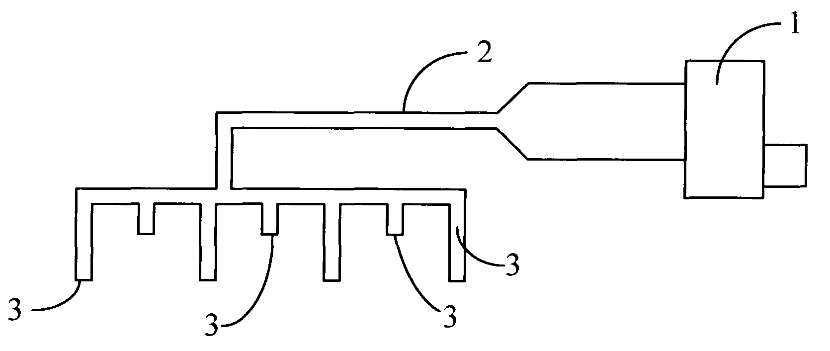
[0040] Fig. 3 shows a schematic diagram of the composition of a specific embodiment of the present invention. It is a split structure fume exhaust device. It includes a blower fan 1 installed outdoors for sucking indoor air, and a variable-diameter exhaust pipe 2 with different diameters at both ends. The variable-diameter exhaust pipe 2 is composed of two sections of pipes with different diameters. The larger end extends out of the room and is connected to the air inlet of the blower fan 1, and the smaller end is connected to the air outlet of the suction part installed indoors for forming local air negative pressure. In this embodiment, the air intake part is composed of a plurality of air intake pipes 3 . One end of each suction pipe 3 is an air outlet, and is jointly connected with the small end of the reduced-diameter exhaust pipe 2 . Each air suction pipe 3 can send the indoor air sucked by the other end into the variable diameter exhaust pipe 2 .

[0041]The variable...

Embodiment 2

[0044] Fig. 5 is a structural principle diagram of a second specific embodiment of the present invention. In the figure, the suction part is two pipe grooves 4, and the air outlets provided on the two pipe grooves 4 are connected with the reduced-diameter smoke exhaust pipe 2 in the same way as the first embodiment above. A plurality of suction holes 41 are also provided on the two pipe grooves 4 . Proper arrangement of the plurality of suction holes 41 can form a local air negative pressure zone around the pipe slot 4 when the fan 1 is working.

[0045] The shape of the pipe groove 4 can be various, it can be linear, it can also be zigzag, and it can also be annular.

[0046] Fig. 6 shows the oil fume exhaust device that adopts this embodiment together with the stove and the cabinet. In the figure, an annular pipe groove 4 is arranged on the edge of the bottom panel of the cabinet a above the stove b, and two pipe grooves 4 are arranged transversely in the middle. Between ...

Embodiment 3

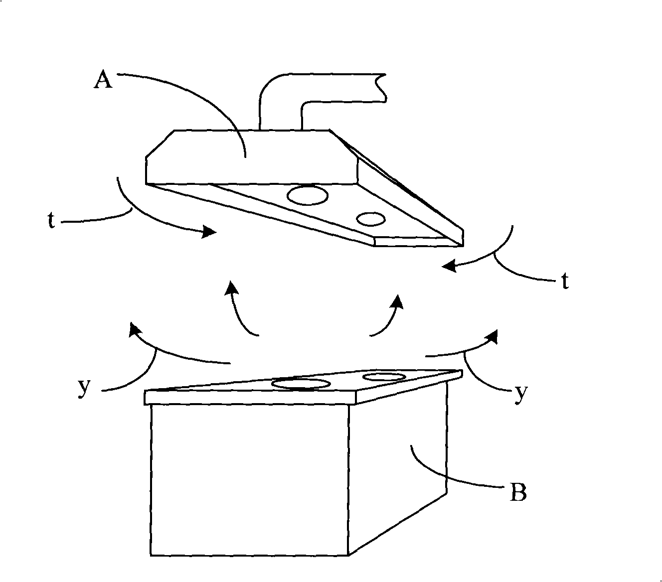
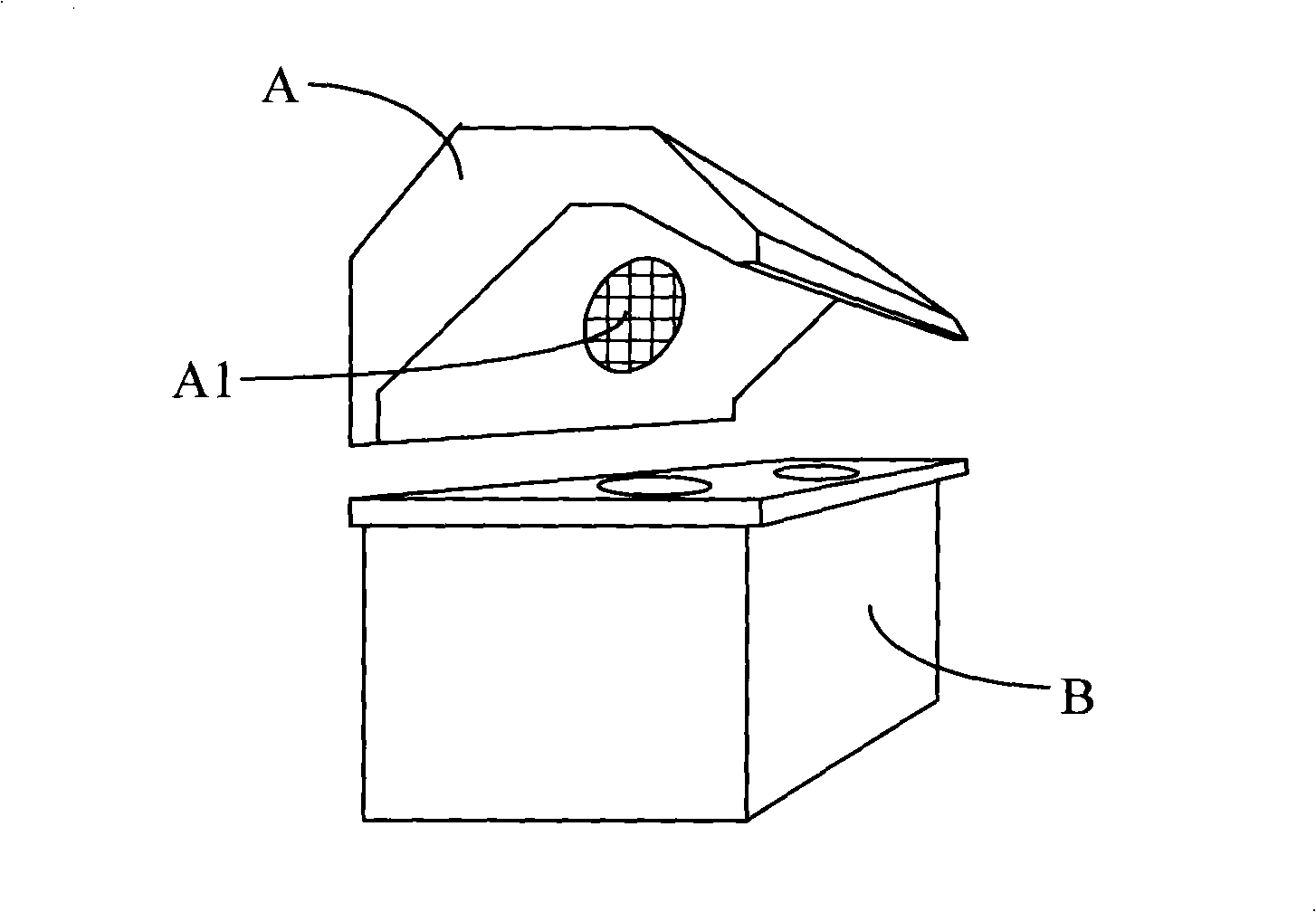
[0049] Fig. 7 shows another structure of the suction part in the third specific embodiment of the present invention. In the figure, the suction part is a fume exhaust plate 5, which is a plate body, and is provided with a recessed part 51 and an air outlet 52 for sucking indoor air on the surface, and one end of the air outlet 52 is connected to the recessed part. 51 is communicated, and the other end is connected with variable-diameter exhaust pipe 2. The shape of the recessed portion 51 is a rectangle, and any other shape can also be adopted. When the fan is started, the air in the recessed part 51 is sucked out through the variable-diameter exhaust pipe 2, forming a negative air pressure in the recessed part 51. A negative pressure area is formed inside, and the external air flows to this area to form a supplementary pressure airflow, and the oil fume generated in this area cannot spread around, and is sucked by the recessed part 51 and then discharged to the outside.

[...


PUM


Abstract

The invention relates to a split fume exhauster, comprising a blower fan mounted outdoors for pumping indoor air, and a reducing exhaust pipe composed of at least two pipes of different diameters, wherein one end at the pipe of larger diameter is connected to an air inlet of the blower fan, and the other end at the pipe of the smaller diameter is mounted indoors and is connected to an air outlet of an air suction part for forming air negative-pressure region; wherein the air suction part is a plurality of air suction pipes, one ends of the air suction pipes are air outlets for sending indoor gas sucked from the other ends into the reducing exhaust pipe. The blower fan of the invention is fixed outdoors, making the kitchen has no machine noise, the exhauster of the invention can control fume spreading, overcomes all defects of the prior exhauster, rapidly and silently, omniberaingly strengthens fume exhausting capability, is convenient to installation, and will not occupy spacing of thekitchen.

Description

[0001] [Note: This application is a divisional application of the invention patent application with the application number 200710195986.2; the application date is December 14, 2007; 】 technical field [0002] The present invention relates to a split-structure oil fume exhaust device, in particular to a device in which the blower and oil suction parts are separately arranged, and the negative pressure area formed by a plurality of negative pressure points in the room effectively captures the oil fume in the air, so that the oil fume cannot A split-structure oil fume exhaust device that spreads to the surroundings and quickly exhausts the outdoors without noise. Background technique [0003] For many years, range hoods of various structures have been widely used in people's daily life as a kind of kitchen equipment. To a certain extent, the environmental pollution caused by oil fume in the kitchen has been removed for people. However, there are still some technical defects in...

Claims


Application Information

Patent Timeline
Patent Type & Authority Patents(China)
IPC IPC(8): F24C15/20
Inventor 王君
Owner 王君
Why Eureka
Try Eureka