
Sucker controller

A controller and sucker technology, which is applied in the direction of magnetic objects, electrical components, load suspension components, etc., can solve the problems of complex demagnetization circuit and long demagnetization time, and achieve the effect of simple demagnetization circuit, fast demagnetization speed and low failure rate

Active Publication Date: 2009-10-07
JIANGSU GAOJING MECHANICAL & ELECTRICAL EQUIPMENT CO LTD
View PDF0 Cites 0 Cited by
  • Summary
  • Abstract
  • Description
  • Claims
  • Application Information

AI Technical Summary

Problems solved by technology

[0003] The invention provides a fast demagnetization method, thereby solving the problems of complex demagnetization circuit and long demagnetization time of the existing sucker controller

Method used


Image

  • Sucker controller

Examples


Embodiment Construction

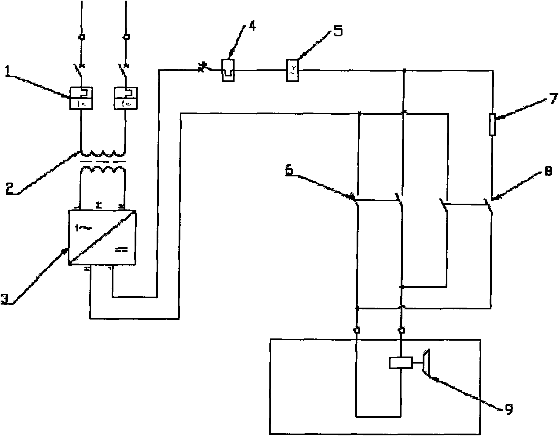
[0010] exist figure 1 Among them, a sucker controller consists of an air switch (1), a transformer (2), a rectifier (3), an air switch (4), a current relay (5), a magnetism relay (6), a demagnetization resistor (7) and Composed of demagnetization relay (8), the air switch (1) is connected in series with the primary side of the transformer (2), after the secondary side of the transformer is connected in series with the rectifier (3), it is connected in series with the air switch (4) and the current relay (5), and then connected with the The demagnetization relay (6) is connected in series with the demagnetization circuit in parallel, and finally connected with the sucker (9); in the demagnetization circuit, the demagnetization resistor (7) is connected in series with the demagnetization relay (8).

[0011] Working principle: When magnetically absorbing, the transformer (2) transforms the input voltage, rectifies it into direct current through the rectifier (3), and then adds it...


PUM


Abstract

The invention relates to the electrical control industry of mechanical processing, in particular to a sucker controller which consists of an air switch, a transformer, a rectifier, an air switch, a current relay, a magnetic-absorbing relay, a demagnetization resistor and a demagnetization relay; the air switch is connected with the primary side of the transformer in series; the secondary side of the transformer is firstly connected with the rectifier in series, later connected with the air switch and the current relay in series, and then connected with a return circuit which is formed by the parallel connection of the magnetic-absorbing relay and a demagnetization return circuit in series, and finally connected with a sucker. The demagnetization resistor and the demagnetization relay in the demagnetization return circuit are connected in series. The sucker controller has the advantages of simple demagnetization return circuit, fast demagnetization speed, and low failure rate.

Description

Technical field: [0001] The invention relates to the electrical control industry of mechanical processing, in particular to a sucker controller. Background technique: [0002] At present, the demagnetization methods of the existing magnetic chuck controllers are all realized by applying gradually decreasing positive and negative polarity voltages to the chuck, the control is complicated, the cost is high, and the demagnetization time is long. Invention content: [0003] The invention provides a fast demagnetization method, so as to solve the problems of complicated demagnetization circuit and long demagnetization time in the existing sucker controller. [0004] In order to achieve the above object, the technical solution of the present invention is: sucker controller, which is composed of air switch, transformer, rectifier, air switch, current relay, magnetism relay, demagnetization resistor and demagnetization relay, and the air switch is connected in series with the prim...

Claims


Application Information

Patent Timeline
Patent Type & Authority Applications(China)
IPC IPC(8): H01F13/00B66C1/06
Inventor 李金友
Owner JIANGSU GAOJING MECHANICAL & ELECTRICAL EQUIPMENT CO LTD
Learn More