High-rotating-speed pulling motor

A traction motor, high-speed technology, applied in the field of lubricating and sealing structure, high-speed traction motor, can solve the problems of easy damage to the transmission end bearing, affecting the lubrication effect, oil channeling, etc. Effect

Inactive Publication Date: 2009-10-07
CRRC YONGJI ELECTRIC CO LTD
View PDF0 Cites 13 Cited by
  • Summary
  • Abstract
  • Description
  • Claims
  • Application Information

AI Technical Summary

Problems solved by technology

[0003] The present invention provides a high-speed traction motor in order to solve the defects and problems existing in the existing motor transmission end, which is prone to "running oil" and affects the lubrication effect, and the transmission end bearing is easily damaged and adopts grease lubrication.

Method used


Image

  • High-rotating-speed pulling motor
  • High-rotating-speed pulling motor
  • High-rotating-speed pulling motor

Examples


Embodiment Construction

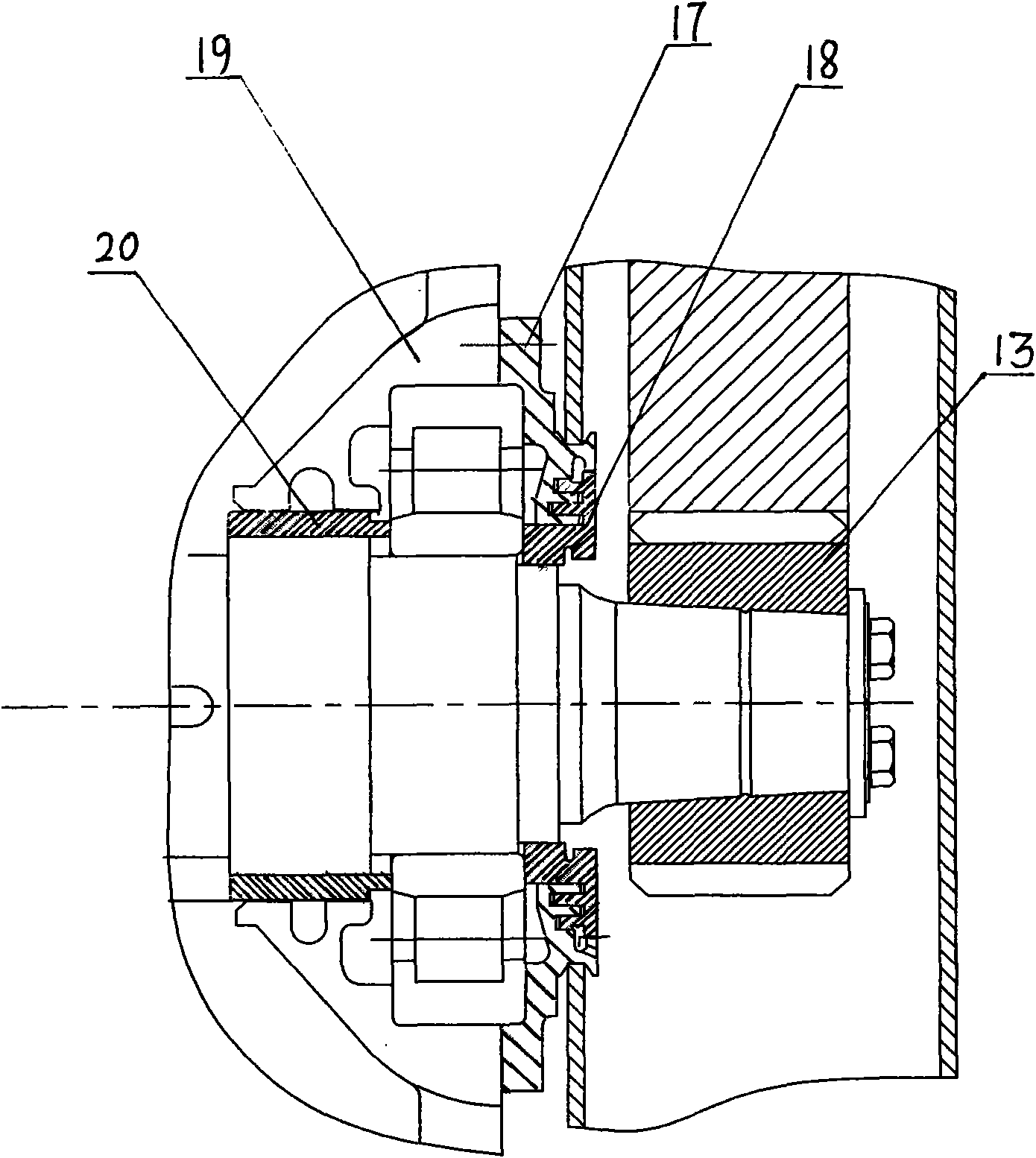
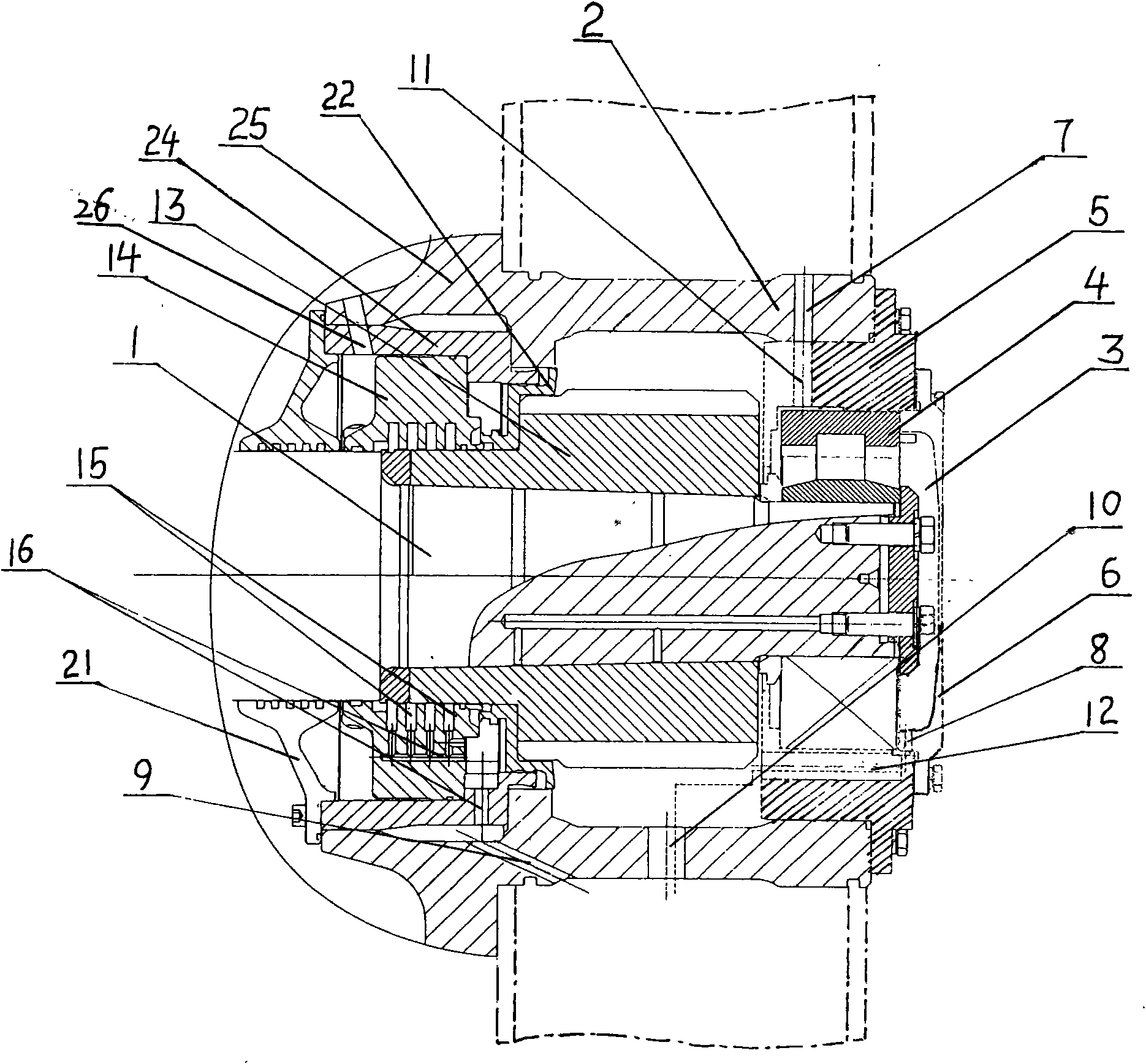
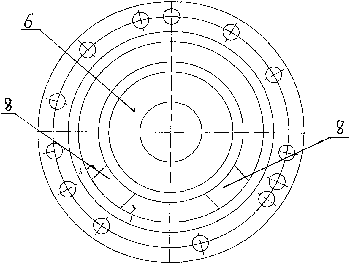
[0015] The high-speed traction motor includes a rotor shaft 1 and an end cover 25. The center of the end cover 25 is provided with a cylindrical sleeve 2 protruding forward. The front end of the rotor shaft 1 is placed in the cylindrical sleeve 2 through a bearing 4. The bearing 4 is sleeved with The bearing inner cover 5 fixed at the front end of the cylindrical sleeve 2, the bearing outer cover 6 fixed on the bearing inner cover 5 is pressed on the front end surface of the bearing 4, the pinion 13 fixed on the rotor shaft 1 is arranged on the rear side of the bearing 4, the pinion 13 is composed of the transmission gear part at the front and the shaft sleeve part at the rear. The cylindrical surface of the cylindrical sleeve 2 has an arc-shaped transmission hole 23 corresponding to the position of the transmission gear of the pinion 13; the top of the cylindrical sleeve 2 has an oil inlet port. Hole 7, the bearing inner cover 5 is provided with an oil through hole 11 communic...


PUM


Abstract

The present invention specifically relates to a high-rotating-speed pulling motor. The invention settles a problem that defects and deficiencies exist in the illogical structure of prior motor. The end cap of high-rotating-speed pulling motor is installed with a cylinder jacket protruding frontwards. A rotor shaft is placed I the cylinder jacket. A bearing is sleeved with a bearing inner cap. The front end surface of bearing is pressed with a bearing outer cover. The back side of bearing is installed with a pinion which is composed of a transmission teeth part and a shaft sleeve part. The cylinder jacket is provided with a transmission opening. The top of cylinder jacket is provided with an oil inlet through hole. The lower part of back end plane of bearing outer cover is provided with a groove. The bearing inner cover is provided with an oil hole which is communicated with the groove and the oil inlet through hole. The shaft sleeve part of pinion is fixed with an oil slinger. The back side of oil singer is provided with a back sealing ring. The back sealing ring is fixed with a protective cover and is provided with a plurality of radial annular sealing grooves. The lower part of annular sealing grooves is provided with an oil leakage channel. The base part of cylinder jacket is provided with a main oil return hole and an auxiliary oil return hole. The high-rotating-speed pulling motor of the invention not only realizes the oil lubrication of bearing, but also overcomes the problem of oil leakage. Simultaneously the service lifetime of bearing is guaranteed.

Description

technical field [0001] The invention relates to a motor, in particular to a lubricating and sealing structure for a bearing at the drive end of the motor, in particular to a high-speed traction motor. Background technique [0002] The traditional lubrication system of traction motors uses grease lubrication for the bearings. A gearbox is installed at the drive end of the motor, and the pinion gear 13 at the drive end of the motor meshes with the large gear of the locomotive in the gearbox and is lubricated with oil. This structure has certain defects in operation: 1. Structural limitations may lead to "oil leakage" phenomenon Occurs, causing motor failure: limited by the structure of the motor, there must be a certain gap between the outer bearing cover 17 and the outer seal ring 18 fixed to the shaft, and the motor cannot be completely sealed with the gearbox. When the motor rotor rotates, a negative pressure will be formed between the end of the motor rotor and the bearin...

Claims


Application Information

Patent Timeline
Patent Type & Authority Applications(China)
IPC IPC(8): H02K7/116H02K5/04H02K5/16
Inventor 张培军尚诗贤魏荣斌
Owner CRRC YONGJI ELECTRIC CO LTD
Why Eureka
Try Eureka