Illumination system

A lighting system and optical system technology, applied in the field of lighting systems, can solve problems such as low efficiency

Inactive Publication Date: 2009-10-07
KONINKLIJKE PHILIPS ELECTRONICS NV
View PDF2 Cites 3 Cited by
  • Summary
  • Abstract
  • Description
  • Claims
  • Application Information

AI Technical Summary

Problems solved by technology

Another drawback is the inefficient coupling of diffused light int

Method used


Image

  • Illumination system
  • Illumination system
  • Illumination system

Examples


Embodiment Construction

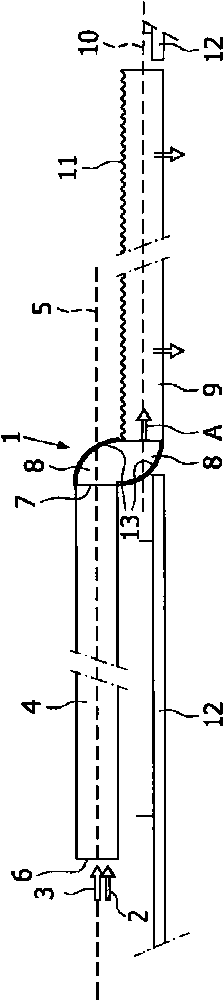
[0017] figure 1 An illumination system is shown that includes two adjacent light sources of different color temperatures, such as fluorescent tubes (not shown), each emitting a light beam with a unique spectrum, such as 2700K and 6500K, during operation. Such a system also comprises an optical system 1 for guiding the light beams 2, 3, the optical system 1 comprising a hollow transparent optical waveguide 4, eg made of glass, the optical waveguide 4 defining a longitudinal optical waveguide axis 5 and having a coupling-in face 6 and outcoupling face 7. The transition part 8 is two connected solid PMMA mirrors in the figure, and this transition part 8 connects the coupling-out face 7 of the optical waveguide 4 to the hollow transparent light-exiting plate 9 . The transparent light extraction plate 9 defines a longitudinal plate axis 10 and has a light extraction structure 11 for coupling out the light beams 2, 3 from these light sources to the outside. Both the optical wavegu...


PUM


Abstract

An illumination system comprising at least two light sources arranged closely together and each emitting a unique light spectrum during operation, and an optical system (1). The optical system comprises an optical waveguide (4) with a coupling-in face (6) and a coupling-out face (7). The optical system further comprises a mirroring transition part (8) connecting the coupling-out face of the optical waveguide to a transparent light extraction panel (9). The transparent light extraction panel has an extraction structure (11) for coupling out light to the exterior. The optical waveguide and the extraction means are specularly reflecting, the mirror preferably being substantially specularly reflecting. Compared with the known illumination systems, the illumination system of the invention is relatively efficient and has an improved control of the light beam.

Description

technical field [0001] The present invention relates to a lighting system according to the preamble of claim 1 . Background technique [0002] Such a lighting system is known from JP2005-183124A. In known lighting systems, diffusers are used to mix different spectra of light so that the system outputs a uniform mixed spectrum and makes the multiple light sources indistinguishable from the outside. The light beams of the light sources of this known system are mixed and diffused in the optical waveguide, resulting in a non-collimated light beam with a Lambertian space light intensity distribution. This diffused light must be coupled into the transition and then into the light exit plate. A Lambertian spatial distribution is an optical distribution of light that obeys Lambert's cosine law, ie has an intensity proportional to the cosine of the angle at which such light is observed. When such a lighting system is used for general lighting purposes and has a transparent light e...

Claims


Application Information

Patent Timeline
IPC IPC(8): G02B6/00F21Y101/00
CPCG02B6/0001G02B6/0068
Inventor P·A·J·霍尔滕P·G·H·科斯特斯D·J·C·范奥尔斯E·布尼坎普
Owner KONINKLIJKE PHILIPS ELECTRONICS NV
Why Eureka
Try Eureka