
Passage wall section for an annular flow passage of an axial turbomachine with radial gap adjustment

A technology of axial-flow turbines and flow channels, which is applied to axial-flow pumps, machines/engines, gas turbine devices, etc., can solve problems such as failure, guide ring warping, space consumption, etc., to avoid warping, uniform force introduction, The effect of reliable adjustability

Inactive Publication Date: 2011-11-16
SIEMENS AG
View PDF6 Cites 4 Cited by
  • Summary
  • Abstract
  • Description
  • Claims
  • Application Information

AI Technical Summary

Problems solved by technology

The disadvantage however is the use of multiple hydraulic cylinders, as each of them may fail
This can lead to warping of the guide ring in case of adjustment
Another disadvantage of this device is that the adjusting force required for axially moving the guide ring is introduced at only three positions by means of the hydraulic cylinder.
Therefore, each cylinder must be able to transmit a large part of the entire adjustment force, which requires space-consuming cylinders

Method used


Image

  • Passage wall section for an annular flow passage of an axial turbomachine with radial gap adjustment
  • Passage wall section for an annular flow passage of an axial turbomachine with radial gap adjustment

Examples


Embodiment Construction

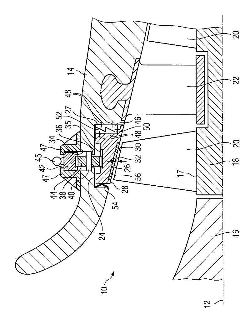
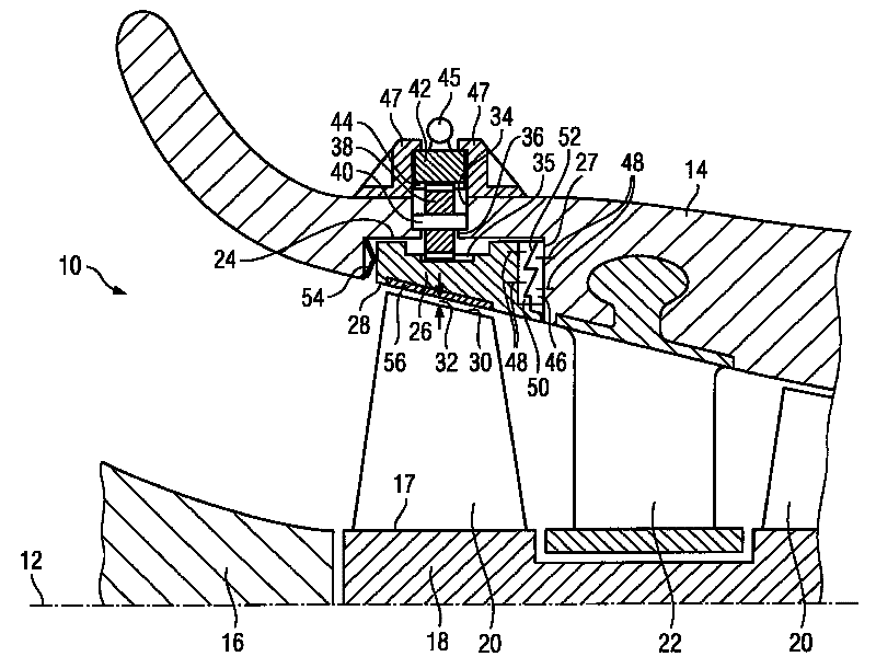
[0017] The single FIGURE shows a section of an annular flow channel 10 in longitudinal section. The annular flow channel 10 extends concentrically along the machine axis 12 of the axially flowing turbine. The turbine shown here is designed as a compressor of a gas turbine. The flow channel 10 includes a wall section 14 which defines the radially outer limit of the flow path. Radially on the inside, the flow path is limited either by the inner wall 16 or by the outer surface of the rotor 18 . The rotor blades 20 are arranged in edge rings at different axial positions on the rotor 18 . Between the two shown rotor blade rings is located a guide vane ring with a plurality of guide vanes 22 distributed over the circumference, which are each held on the duct wall section 14 by means of hammer-shaped fastening elements.

[0018] in the compressor at the figure 1 Upstream of the flow channel 10 , which flows from left to right, a guide ring 26 consisting of several segments is arr...


PUM


Abstract

The invention provides a passage wall section (14) of an annular flow passage (10) of an axial turbomachine with which a simple and reliable adjustment of a radial gap between the inner wall surface (28) of a guide ring (26) and a rotor blade tip (30) oppositely arranged on the wall surface (28) is possible. The guide ring (26) has a first toothing arrangement (20) which is in contact with a second toothing arrangement (46) arranged on a sidewall (27) of a circumferential groove (24) which accommodates the guide ring (26), wherein for axial displacement of the displaceable guide ring (26), the guide ring is rotatable in a circumferential direction.

Description

technical field [0001] The invention relates to a channel wall section of an annular flow channel of an axial turbomachine with a radial gap adjustment function. Background technique [0002] Such flow channels are disclosed in various forms. For example, US Pat. No. 5,203,673 discloses such a device for controlling and adjusting the radial gap between the tips of rotor blades and a guide ring situated opposite it, which is part of the channel wall. It is proposed here that the guide ring can be moved axially in the conical flow channel for adjusting the radial gap. To displace the guide ring in the axial direction, three hydraulic cylinders, the pistons of which are movable parallel to the machine axis of the turbomachine, are screwed into the guide vane carrier distributed over the circumference. In combination with the conical gap between the wall surface of the guide ring that limits the flow path and the tips of the rotor blades that are inclined accordingly, it is po...

Claims


Application Information

Patent Timeline
Patent Type & Authority Applications(China)
IPC IPC(8): F01D11/22F04D19/00F02C3/06
CPCF01D11/22
Inventor R.格雷费C.考夫曼R.拉比施M.林克O.施奈德
Owner SIEMENS AG
Learn More