Check patentability & draft patents in minutes with Patsnap Eureka AI!

An ambient lighting system for a display device

A technology for ambient lighting and display equipment, applied in the field of ambient lighting systems

Inactive Publication Date: 2011-06-08
TP VISION HLDG
View PDF7 Cites 2 Cited by
  • Summary
  • Abstract
  • Description
  • Claims
  • Application Information

AI Technical Summary

Problems solved by technology

A total of 8 pixels seems to be the upper limit for cost reasons

Method used


Image

  • An ambient lighting system for a display device
  • An ambient lighting system for a display device
  • An ambient lighting system for a display device

Examples


Embodiment Construction

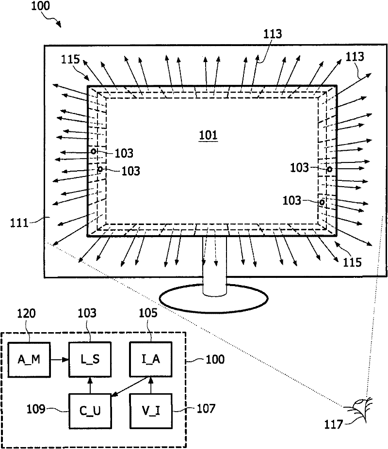
[0076] figure 1 An ambient lighting system 100 according to the invention is shown for a display device comprising an image display area 101, suitable for integration into a new or existing display device (eg a television). The display device may be a computer monitor, a cathode ray tube (CRT) display, a liquid crystal display (LCD), an organic LED display (OLED), a plasma discharge display, a projection display, a thin film printed optically active display, or use a functionally equivalent display technology monitors.

[0077] The ambient lighting system 100 comprises a video input (V_I) 107 for receiving video data to be displayed on a display device, an image analyzer (I_A) 105 for determining color information from the received video data; arranged in an array 115 A substantially point-shaped and controllable light source (L_S) 103, and a control unit (C_U) for controlling the emission color of the light source based on the determined color information. The color informa...


PUM


Abstract

This invention relates to an ambient lighting system for a display device including an image display region. Controllable light sources that are substantial point-like and disposed in an array are provided, each being adapted to emit a light beam of at least one wavelength onto an region visually appearing to the viewer peripherally surrounding the display. An image analyzer determines the color information from video data of the displayed image, the color information being used as a control parameter for controlling the emission color of the emitted light beams. Due to the substantial point-like property of the light sources along with their arrangement within the array the emitted light beams onto the region forms a pixelated image so as to provide at least a partial extension of the image display region.

Description

technical field [0001] The present invention relates to an ambient lighting system for a display device comprising an image display area, and to a display device comprising such an ambient lighting system. Background technique [0002] EP1551178 discloses so-called Ambilight, which is a concept to enhance the viewing experience when watching TV by means of ambient lighting. The image extends beyond the boundaries of the TV screen. This concept (feature) has recently been introduced into the market and has been found to have a huge positive impact on the sales of high end LCD TVs equipped with this feature. [0003] In the concept of an ambient light source, as currently implemented, an extension of the image is projected onto the wall behind the TV by means of a low-pressure gas discharge lamp such as a CCFL (cold cathode fluorescent) lamp located behind the TV. Each lamp creates a "pixel" of light on the wall behind the display (or on a dedicated diffuse reflective or dif...

Claims


Application Information

Patent Timeline
Patent Type & Authority Patents(China)
IPC IPC(8): H04N9/73H05B47/105
CPCG02B6/001H04N9/73
Inventor M·P·C·N·克里恩B·A·萨尔特斯W·F·J·胡根斯特拉滕
Owner TP VISION HLDG
Features
  • R&D
  • Intellectual Property
  • Life Sciences
  • Materials
  • Tech Scout
  • Unparalleled Data Quality
  • Higher Quality Content
  • 60% Fewer Hallucinations
Learn More