
Device for making a combed fiber web

A technology of fiber webs, equipment, applied in the direction of fiber processing, combing machines, textiles and paper making, to achieve the effect of simple manufacturing tolerances

Active Publication Date: 2009-10-14
MASCHINENFABRIK RIETER AG
View PDF2 Cites 7 Cited by
  • Summary
  • Abstract
  • Description
  • Claims
  • Application Information

AI Technical Summary

Problems solved by technology

However, this movement must be precisely coordinated with the feed of new fiber material for optimum carding work and optimum separation operation

Method used

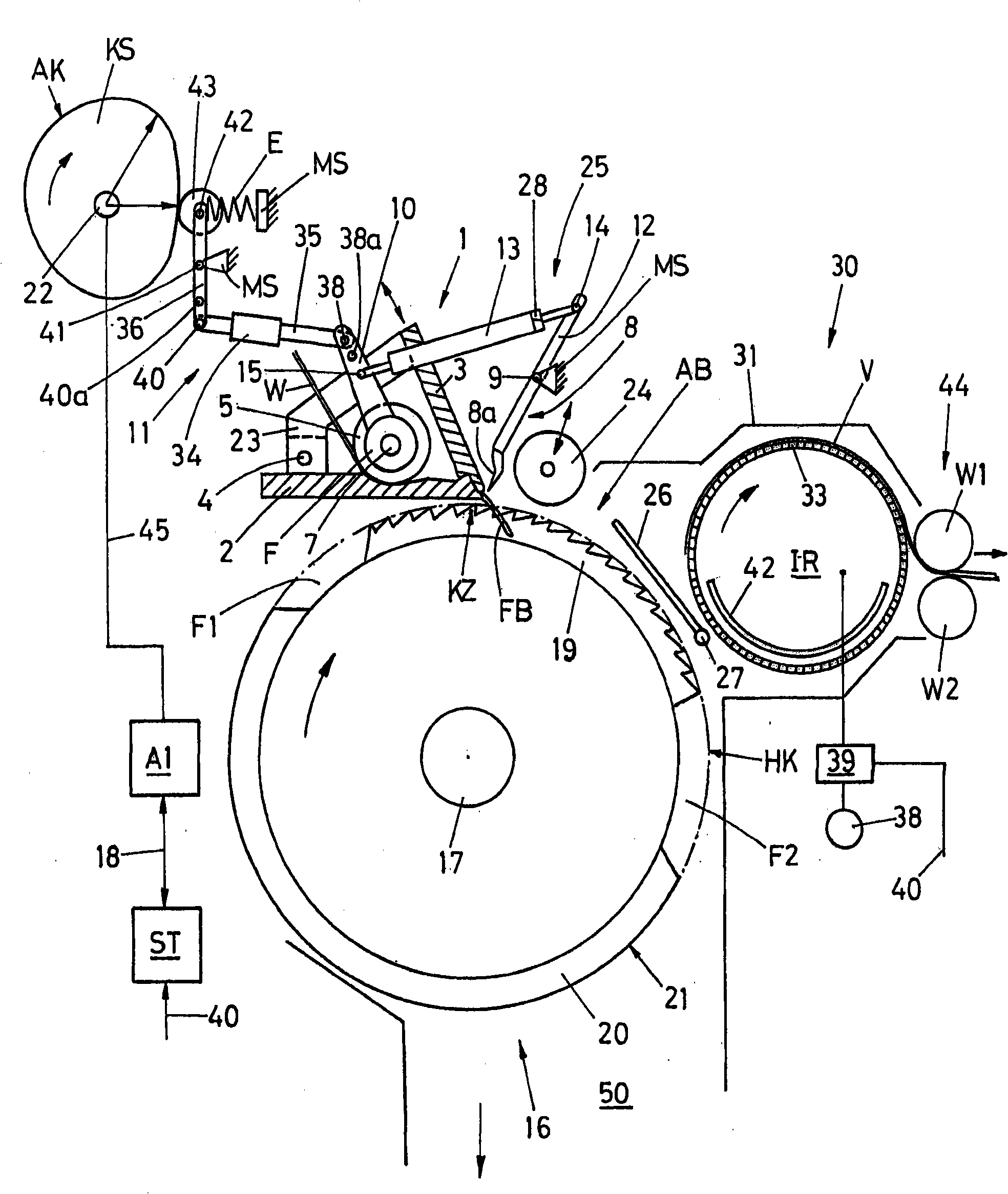

Image

  • Device for making a combed fiber web
  • Device for making a combed fiber web
  • Device for making a combed fiber web

Examples


Embodiment Construction

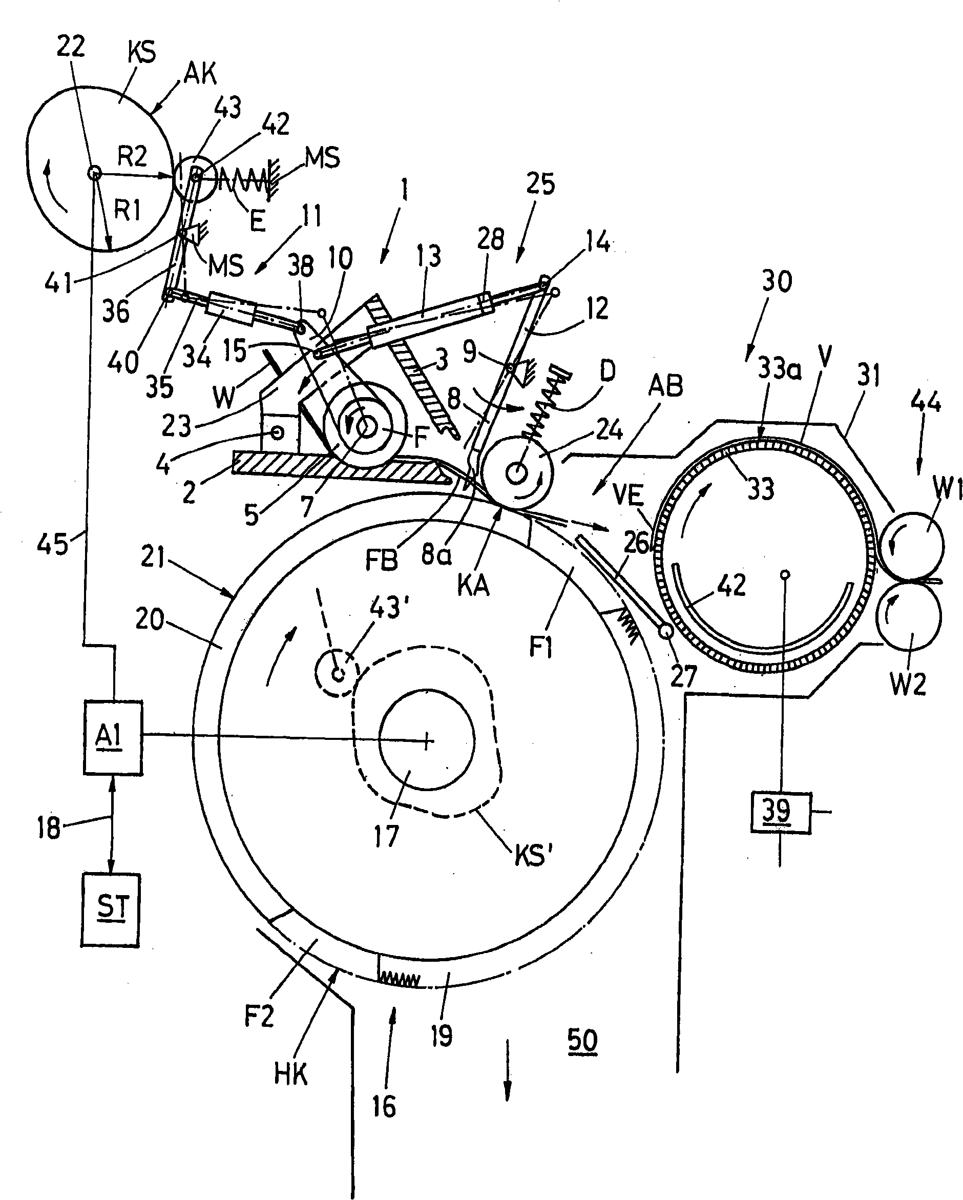
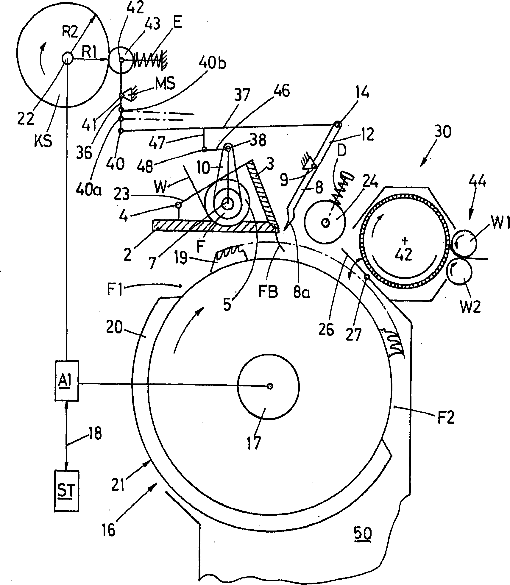
[0030] figure 1 Shown is a jaw assembly 1 of a combing machine (referred to simply as nipper) with a substantially stationary lower nipper 2 and with nippers 3 mounted movably relative to the lower nipper. In this example, the nipper blade 3 is fixed on an arm 23 pivotably mounted about an axis 4, which arm is fixed in the frame or on the lower nipper plate 2, as shown.

[0031] In the illustration shown, the tongs are closed, the nipper blade 3 and the lower nipper 2 form a nip point KZ for clamping a sliver W.

[0032] The sliver W can be formed, for example, from a sliver sheet unwound from a sliver roll, not shown in detail. It is also possible for the sliver W to consist of one or more fiber slivers (sliver) supplied next to each other. In the case of using fiber slivers, the fiber slivers are fed from cans installed at the combing machine. This example shows only one grooming head.

[0033] Generally, however, a plurality of such carding heads are arranged side by si...


PUM


Abstract

The present invention relates to a device for making a combed fiber web, which comprises a fixed gripper aggregate (1) with a lower nipper plate (2) and an upper knife (3); a feed mechanism (5) that be driven intermittently and mounted inside the gripper aggregate (1) in a rotary way for supplying fiber material to clamp point of the gripper aggregate; a combing roller that mounted below the gripper aggregate in a rotating way and circumference of which is provided with a combing section (19) and a removing section (20); a removing roller (24) that mounted in a rotating way can move towards the removing section and followed by a fiber forming equipment (30); also comprises a top comb (8) that movably supported between the aggregate and the roller. The feed mechanism (5) and the top comb are driven by a cam disk (KS) and a shaft (22), which are connected with a drive (A1). Drive elements (36, 35, 10) of the feed mechanism (5) are directly coupled with drive elements (13, 12) of the top comb (8).

Description

technical field [0001] The invention relates to a device for forming a carded fiber web from a fiber material according to the preamble of claim 1 . Background technique [0002] In the case of a comber working on the Heilmann principle, various publications are known from the prior art which show the use of a top comb (fixed comb) direction to move. Such a device is known, for example, from DE-PS2433062, which shows several variants comprising fixed or movably mounted clamps and fixed or movably mounted detaching rollers with movably mounted top combs. combination. The feeding of the fibrous material is poorly described in this publication. [0003] CH-PS150873 discloses a design in which the top comb is arranged to move with the detaching roller or with the clamp assembly. [0004] US-PS1944944 also discloses a design in which the top comb is designed to move in the direction of the clamp assembly together with the detaching roller. [0005] From the two last-mentione...

Claims


Application Information

Patent Timeline
Patent Type & Authority Applications(China)
IPC IPC(8): D01G19/10D01G19/16D01G19/26
CPCD01G19/10D01G19/26D01G19/08D01G19/28
Inventor D·索默U·斯图茨
Owner MASCHINENFABRIK RIETER AG
Learn More