
Hydraulic pump

A hydraulic pump and hydraulic system technology, applied in the field of hydraulic pumps, can solve problems such as inability to ensure performance and increase the overall cost of finished pumps

Inactive Publication Date: 2012-05-30
DAB PUMPS SPA
View PDF0 Cites 0 Cited by
  • Summary
  • Abstract
  • Description
  • Claims
  • Application Information

AI Technical Summary

Problems solved by technology

[0013] In order to prolong the service life of pumps with cast iron pump bodies, anti-corrosion treatment is carried out on said pump bodies, which increases the overall cost of the finished pump, and in terms of durability time, it cannot in any case ensure the same as that made by stainless steel pump bodies. achieved performance

Method used


Image

  • Hydraulic pump
  • Hydraulic pump
  • Hydraulic pump

Examples


Embodiment Construction

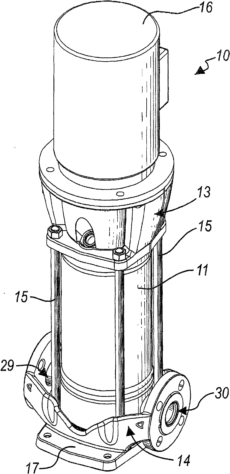
[0025] Referring to the drawings, a hydraulic pump according to the invention is indicated generally by the reference numeral 10 .

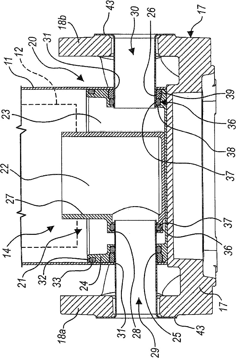
[0026] The hydraulic pump 10 includes a casing 11 for containing an impeller assembly 12 in image 3 is schematically shown in dotted lines in ; in this embodiment, the pump is a multistage vertical pump and the impeller assembly corresponds to the multistage impeller.

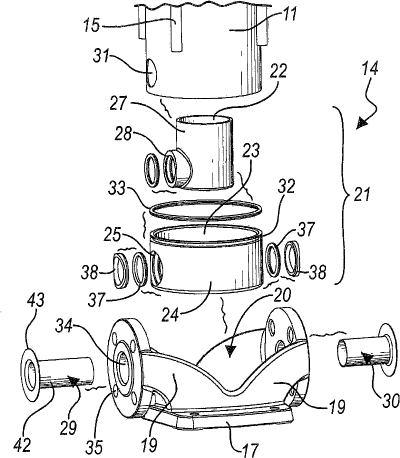
[0027] The casing 11 (which has a cylindrical shape) is closed at its ends by a top cover 13 and a pump body 14 for connecting to a hydraulic system, respectively, as in figure 2 clearly visible in.

[0028] The top cover 13 and the connecting pump body 14 are connected by tension elements 15 in a manner known per se.

[0029] The motor 16 is externally fixed to the top cover 13 and its outer shaft passes through the top cover 13 to connect with the impeller assembly 12 inside the casing 11 .

[0030] According to the invention, the connecting pump body 14 comprises a base 17...


PUM


Abstract

A hydraulic pump (10), of the type which comprises a jacket (11) for containing an impeller assembly (12), which is closed at its ends respectively by a closure head (13) and by a pump body (14) for connection to the hydraulic system. The pump body (14) comprises a footing (17) from which two mutually opposite flanges (18a, 18b) for fixing the pump to the hydraulic system protrude monolithically with respect to the footing ( 17). A box-like body (21 ) is arranged on the footing (17) and forms internally two mutually isolated chambers (22, 23) which are open upward, respectively a first chamber(22) for sending fluid into the impeller assembly (12) and a second chamber (23) for collecting the fluid that arrives from the impeller assembly ( 12). The pump body ( 14) further comprises two sleeves (29, 30), a first intake sleeve (29), which protrudes from the first chamber (22) and is associated at one end with a first one (18a) of the flanges, and a second delivery sleeve (30), which protrudes from the second chamber (23) and is associated at one end with the second ( 18b) of the flanges. The space formed by the contour of the footing (17) which is comprised between the jacket ( 11) and the flanges (18a, 18b) and is occupied by the sleeves (29, 30) is open upward.

Description

technical field [0001] This invention relates to hydraulic pumps, particularly but not exclusively to multi-stage vertical hydraulic pumps. Background technique [0002] It is known that the hydraulic pumps of user hydraulic systems of various specifications generally consist of a steel housing on which the chambers of the water inlet and outlet and the impeller assembly (with one or more impellers, depending on the number of stages) are formed, and the electric motor is connected to the housing and arranged on the inside or outside of the housing. [0003] Generally speaking, the casing of a vertical hydraulic pump is generally composed of a casing containing an impeller assembly, and the two ends of the casing are respectively closed by a top cover and a pump body for connecting to a hydraulic system. [0004] An inlet and an outlet are formed on the connecting pump body and are functionally connected to the inlet and outlet of the impeller assembly, respectively. [000...

Claims


Application Information

Patent Timeline
Patent Type & Authority Patents(China)
IPC IPC(8): F04D1/06F04D29/42F04D29/62
Inventor F·西尼科A·L·穆勒
Owner DAB PUMPS SPA
Learn More