Intermediate casing of turbojet

A turbojet, intermediate box technology, applied in engine components, machines/engines, jet propulsion, etc., can solve problems such as large size and damage to engine aerodynamic performance

Active Publication Date: 2009-10-21
SN DETUDE & DE CONSTR DE MOTEURS DAVIATION S N E C M A
View PDF1 Cites 5 Cited by
  • Summary
  • Abstract
  • Description
  • Claims
  • Application Information

AI Technical Summary

Problems solved by technology

Not only that, but the excessive volume of such lever arms impairs the aerodynamics of the engine

Method used


Image

  • Intermediate casing of turbojet
  • Intermediate casing of turbojet
  • Intermediate casing of turbojet

Examples


Embodiment Construction

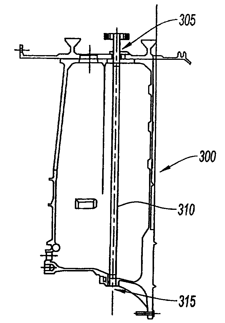
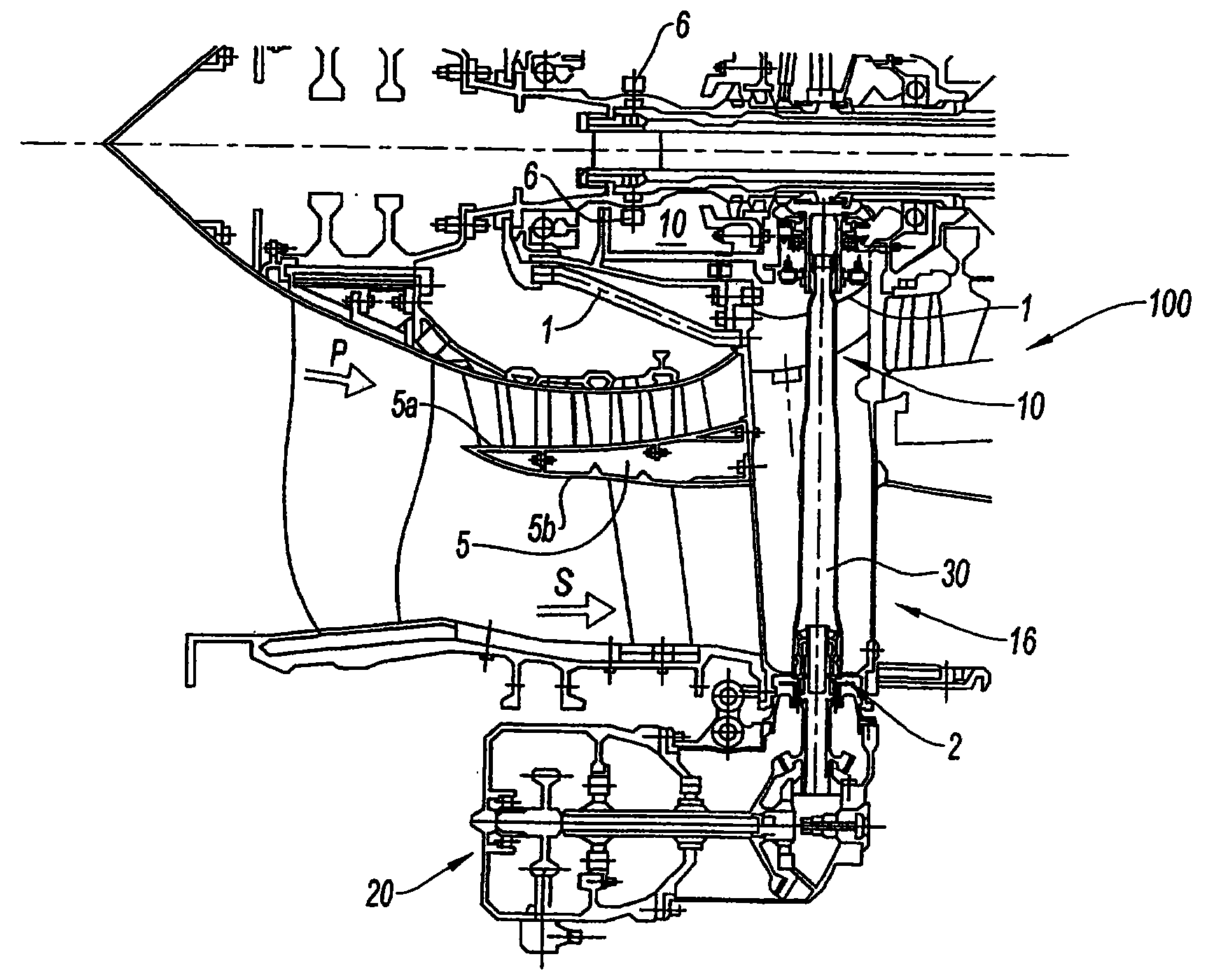
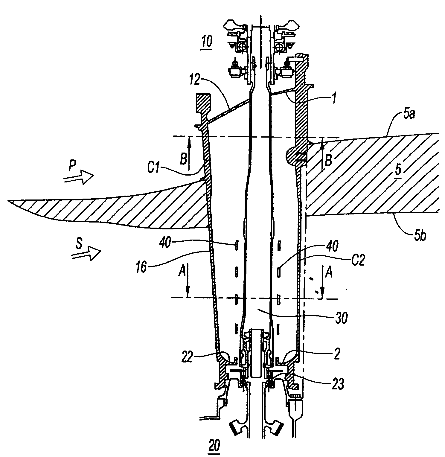
[0030] An embodiment of the present invention is now described with reference to the accompanying drawings: figure 2 Shown is an intermediate box 100 with a central hub 1 and an outer casing 2 connected by a radial arm 16 arranged vertically on the lower part. This central hub 1 partly delimits the volume of the turbojet engine's front wall 10 in which the bearings 6 supporting the low pressure (BP) and high pressure (HP) rotor shafts are housed. An auxiliary machine drive box 20 is mounted on the cylindrical outer casing 2 of the box 100, these auxiliary machines are driven by an integral transmission shaft 30 mounted in the radial lever arm 16 for obtaining the Power supported on the BP and HP rotor shafts in the front wall 10.

[0031] A separator 5 delimits the second gas flow S and the first gas flow P. The separator is formed by two annular walls 5a, 5b separated by a radial arm 16 through which the cross-section of the first air flow is smaller relative to the cross-...


PUM


Abstract

The invention relates to the turbojet field, especially a turbojet with a plurality of air current or two air current. The intermediate casing of a turbojet includes: a plurality of radial directional arms (16) with at least one hollow and a radial directional transmission shaft (30) rotatably installed in the radial directional arms (16) and driving an auxiliary machine (20), the radial directional arms are suited between an inside hub (1) and an outside cylindrical shroud (2), a first end part of the transmission shaft (30) penetrates through the inside hub (1), and a second end part penetrates through the outside cylindrical shroud (2). The casing is characterized in that a housing is characterized by being composed of a single compartment whose content unit volume stores the transmission shaft (30), and forms a passage for a lubricating fluid.

Description

technical field [0001] The invention relates to the field of turbojet engines, in particular turbojet engines with multi-flow and in particular with double-flow. Background technique [0002] Civilian twin-flow turbojet engines are used to drive commercial aircraft that ensure passenger and cargo transportation, and generally include a front blast rotor, the output airflow is divided into two concentric airflows, a first airflow and a second airflow. This first airflow is directed to the turbine engine, which drives, among other things, the blower rotor; the second airflow is discharged directly into the atmosphere to provide a large part of the thrust, and may be mixed with the hot first airflow downstream of the turbine before injection. [0003] A turbine engine consists of multiple stages of additional compression, a combustion stage and multiple stages of turbines, the latter of which drives the blast. [0004] Said devices ensuring the operation of the engine are cont...

Claims


Application Information

Patent Timeline
IPC IPC(8): F01D25/16F01M11/02F02K3/00
CPCF02C7/32F01D25/18F01D25/162F01D9/065Y02T50/60
Inventor 蒂埃里·杜彻戴勒菲利普·沃瑟斯
Owner SN DETUDE & DE CONSTR DE MOTEURS DAVIATION S N E C M A
Why Eureka
Try Eureka