Piston-type leak stop

A water leakage protection, piston-type technology, applied in the direction of pipes/pipe joints/fittings, mechanical equipment, pipe components, etc., can solve the problems of high production cost, short life, unstable reliability, etc.

Inactive Publication Date: 2009-11-04
沈琦
View PDF0 Cites 4 Cited by
  • Summary
  • Abstract
  • Description
  • Claims
  • Application Information

AI Technical Summary

Problems solved by technology

[0003]In order to overcome the shortcomings of high production cost, troublesome installation and maintenance,

Method used


Image

  • Piston-type leak stop
  • Piston-type leak stop
  • Piston-type leak stop

Examples


Embodiment 1

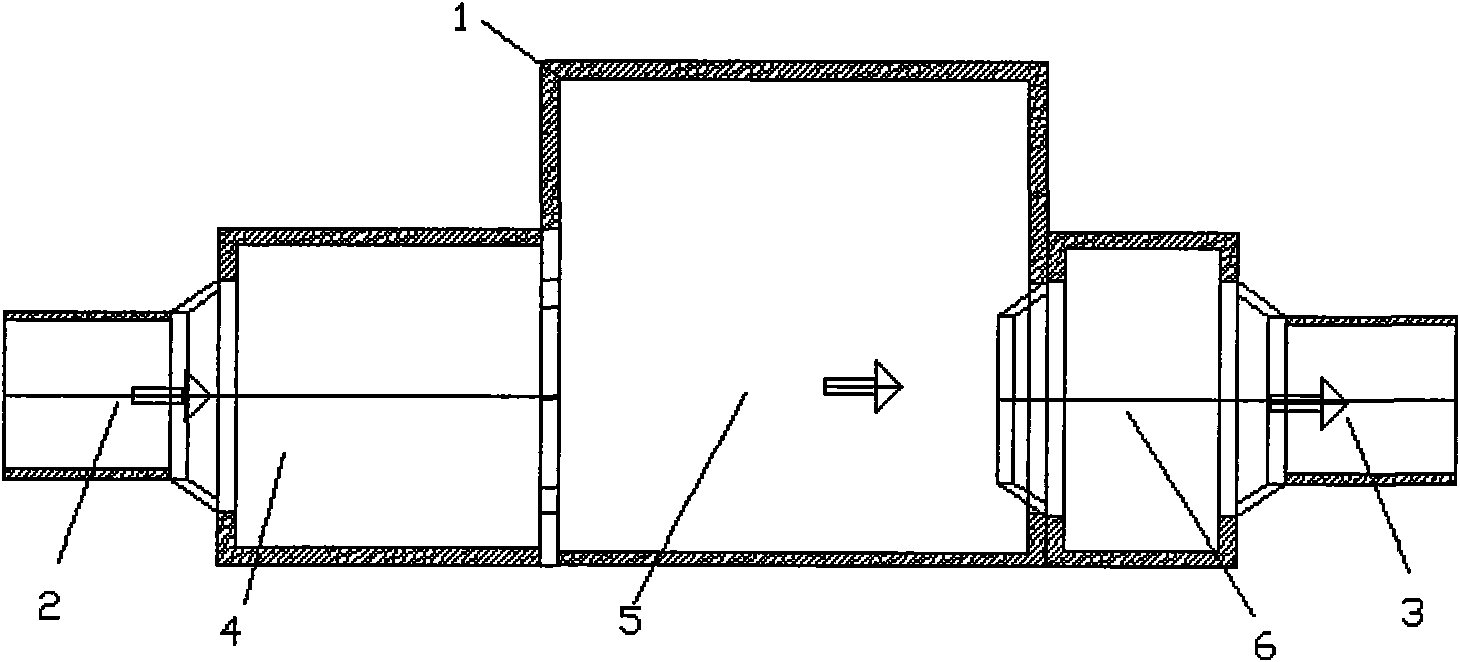
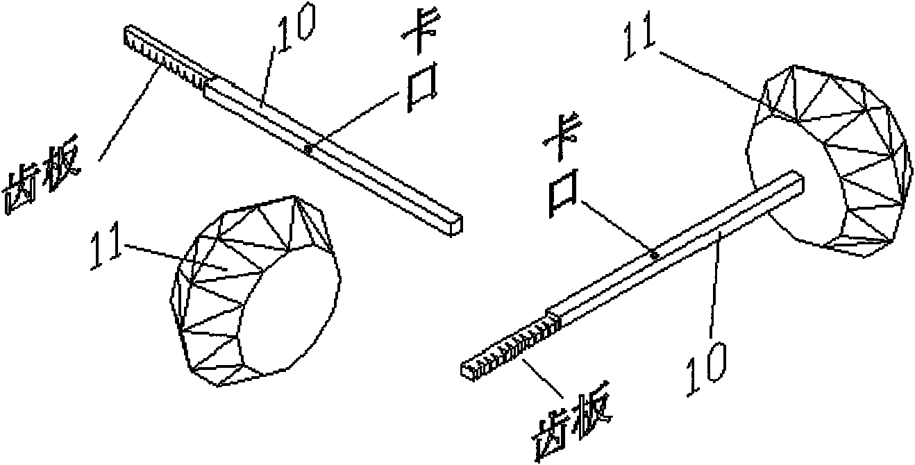
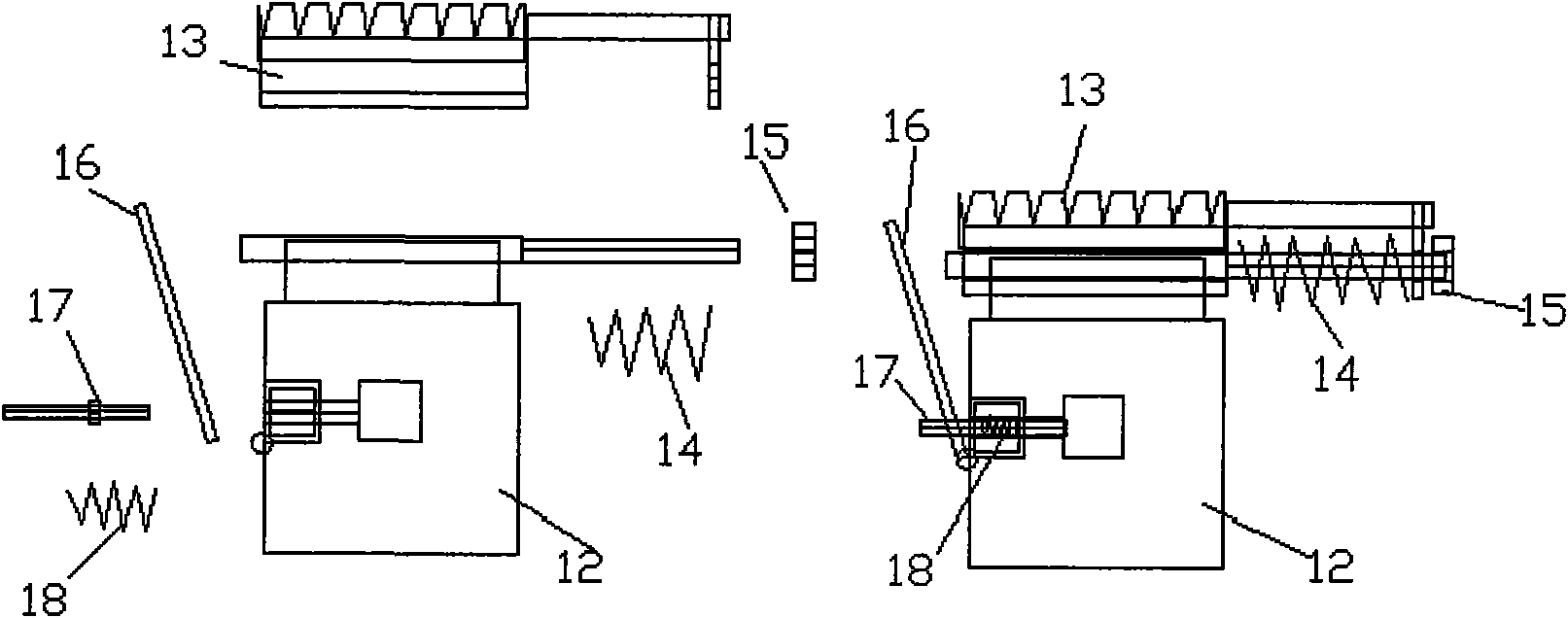
[0025] The piston type water leakage protector in the present embodiment is made up of casing (1), impeller, piston, movable base and reduction gear set. The impeller is set in the impeller chamber (4) of the casing (1), the transmission gear (9) on the impeller and the primary transmission gear (21) in the reduction gear set in the control chamber (5) of the casing (1) ) bite, when the impeller is installed, the direction of the impeller shaft (7) and the direction of the water inlet are on the same straight line (such as Figure 6 shown). The return spring (14) in the movable base is inserted into the rod of the base (12), then the tooth plate guide groove (13) is inserted into the guide rail on the base (12), and finally the nut (15) is screwed on, and the door seal in the piston The rod (10) and the two-way sealing door (11) are connected as a whole, and the sealing rod (10) is inserted into the return spring (19) and passed through the support (d), and then inserted into...


PUM


Abstract

The invention relates to a piston-type leak stop. The stop comprises a shell, an impeller, a piston, a movable base and a reduction gear set. Water impels the piston to drive a toothed plate guide slot in the movable base and a final-stage gear in the reduction gear set to engage with each other, and the final-stage gear in the reduction gear set transfers torsion to the toothed plate guide slot to mobilize the toothed plate guide slot so as to control separation of a door closing rod in the piston and the movable base, thus realizing a function of automatic stopping of water leakage. Water leakage is determined based on flow rate of water continuously passing through the piston-type leak stop at one time, and the flow rate of water can be set.

Description

technical field [0001] The invention relates to an anti-leakage device, in particular to a purely mechanical device for detecting water leakage and automatically cutting off to prevent water leakage. Background technique [0002] At present, in the field of water use, due to the aging of the water pipe network and the damage of external force, or the damage of the water device connected to the pipeline, or the water leakage caused by forgetting to turn off the water device, etc., water leakage is common. The products developed for detecting water leaks are all electronic products. Its production cost is high, users have to maintain it frequently, and installation is also troublesome. Electronic products have relatively high environmental requirements, which will directly affect the reliability and life of the device. Contents of the invention [0003] In order to overcome the shortcomings of high production cost, troublesome installation and maintenance, unstable reliabil...

Claims


Application Information

Patent Timeline
IPC IPC(8): F16L55/10
Inventor 沈琦
Owner 沈琦
Why Eureka
Try Eureka