
High pressure resistant rotary electromagnet with low inertia

A rotating electromagnet, high-voltage technology, applied in the direction of electromagnets, electrical components, electromechanical devices, etc., can solve the problem of inability to work in wet state, and achieve the effect of maintaining accuracy, fast response speed and long system life

Inactive Publication Date: 2009-11-04
ZHEJIANG UNIV OF TECH
View PDF0 Cites 23 Cited by
  • Summary
  • Abstract
  • Description
  • Claims
  • Application Information

AI Technical Summary

Problems solved by technology

[0004] In order to overcome the shortcomings of the existing electro-mechanical converters for electro-hydraulic digital valves, which have no seal and high-voltage resistance structure and cannot work in wet conditions, the present invention provides a high-voltage resistance structure with good high-voltage resistance characteristics and suitable for working in wet conditions. Low inertia rotating electromagnet

Method used


Image

  • High pressure resistant rotary electromagnet with low inertia
  • High pressure resistant rotary electromagnet with low inertia
  • High pressure resistant rotary electromagnet with low inertia

Examples


Embodiment Construction

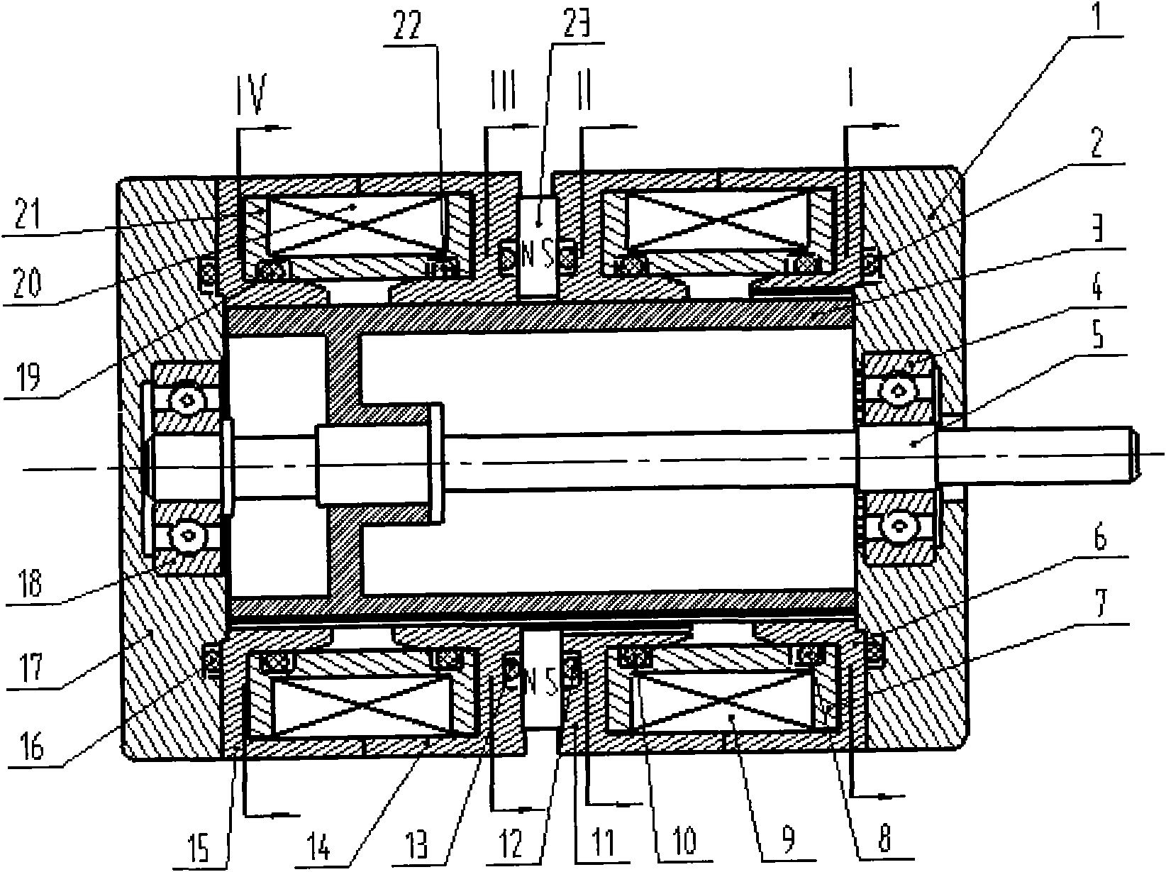
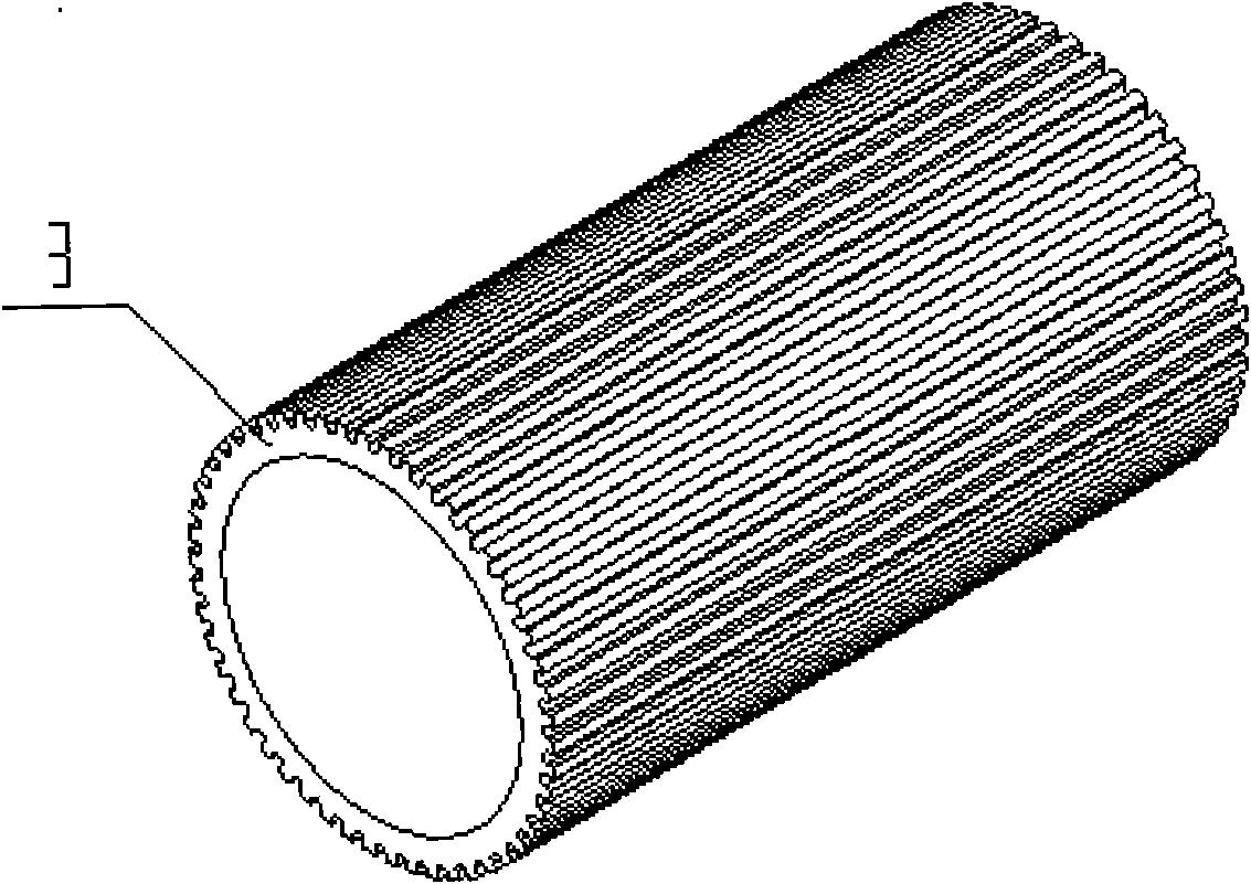
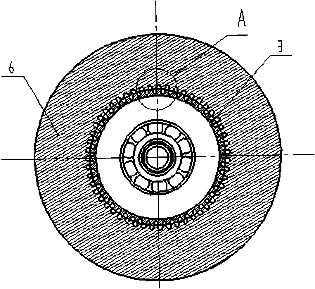
[0020] The present invention will be further described below in conjunction with the accompanying drawings.

[0021] refer to Figure 1 ~ Figure 4e , a high-pressure-resistant low-inertia rotating electromagnet, including a stator part, a rotor part, a front end cover 1 and a rear end cover 17, the stator part is located outside the rotor part, the rotor part includes a rotor and a rotor shaft, and the rotor is mounted on On the rotor shaft 5, the two ends of the rotor shaft 5 are installed on the front end cover 1 and the rear end cover 17 respectively, and the stator components include a first stator core 6, a second stator core 11, a third stator core 14, The fourth stator core 15, the first magnetic isolation ring 7, the second magnetic isolation ring 21, the first control coil 9, the second control coil 20 and the permanent magnet 23, the first stator core 6, the second stator core 11 , the third stator core 14, and the fourth stator core 15 are all semi-open, and the fi...


PUM


Abstract

The invention relates to a high pressure resistant rotary electromagnet with low inertia, comprising a stator part, a rotor part, a front end cover and a rear end cover; wherein, the stator part comprises four stator cores, a first magnetism isolating ring, a second magnetism isolating ring, a first control coil, a second control coil and a permanent-magnet; the stator cores are distributed at the outer ring of the rotor in a shape of half opening, openings of the first and the second stator cores are corresponding to each other and form a first cavity, and the first magnetism isolating ring is positioned inside the first cavity; openings of the third and the fourth stator cores are corresponding to each other and form a second cavity, and the second magnetism isolating ring is positioned inside the second cavity; the permanent-magnet is positioned between the second stator core and the third stator core and is magnetized to be N and S poles along the axial direction; the outer circumference surface of the rotor are provided with rotor teeth having the number being the same as that of all the stator cores. The invention has good high pressure resistant property, and is suitable for working in a wet state.

Description

technical field [0001] The invention belongs to an electro-mechanical converter for an electro-hydraulic digital valve in the field of fluid transmission and control, and in particular relates to a high-voltage-resistant and low-inertia rotating electromagnet. Background technique [0002] Electric-mechanical converters for valves can be divided into dry type and wet type according to whether there is oil in the working chamber of the armature. Therefore, it has the advantages of good heat dissipation, small friction, low impact noise when reversing and resetting, stable operation and long life, so it is widely used. [0003] Conventional electro-hydraulic digital valve electric-mechanical converter is a hybrid stepper motor controlled by AC servo mode. There is no sealed high-pressure structure between the control coil and the rotor working chamber. Once the oil enters the working chamber, the control coil The motor will be directly immersed in the oil, which will cause da...

Claims


Application Information

Patent Timeline
IPC IPC(8): H01F7/06H02K33/00
Inventor 阮健孟彬
Owner ZHEJIANG UNIV OF TECH
Learn More