Stacking type electronic component and manufacturing method thereof

A technology of electronic components and manufacturing methods, applied in the field of laminated electronic components and its manufacturing, capable of solving problems such as disconnection of the connecting part of a through-hole conductor and a coil conductor, and achieving the effect of suppressing disconnection

Active Publication Date: 2009-11-04
MURATA MFG CO LTD
View PDF6 Cites 7 Cited by
  • Summary
  • Abstract
  • Description
  • Claims
  • Application Information

AI Technical Summary

Problems solved by technology

However, in Patent Document 1, there is no mention of the disconnection of the connection portion between the via-hole conductor and the coil conductor.

Method used


Image

  • Stacking type electronic component and manufacturing method thereof
  • Stacking type electronic component and manufacturing method thereof
  • Stacking type electronic component and manufacturing method thereof

Examples


Embodiment Construction

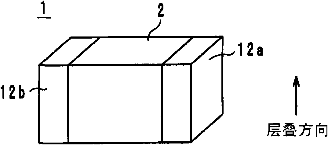
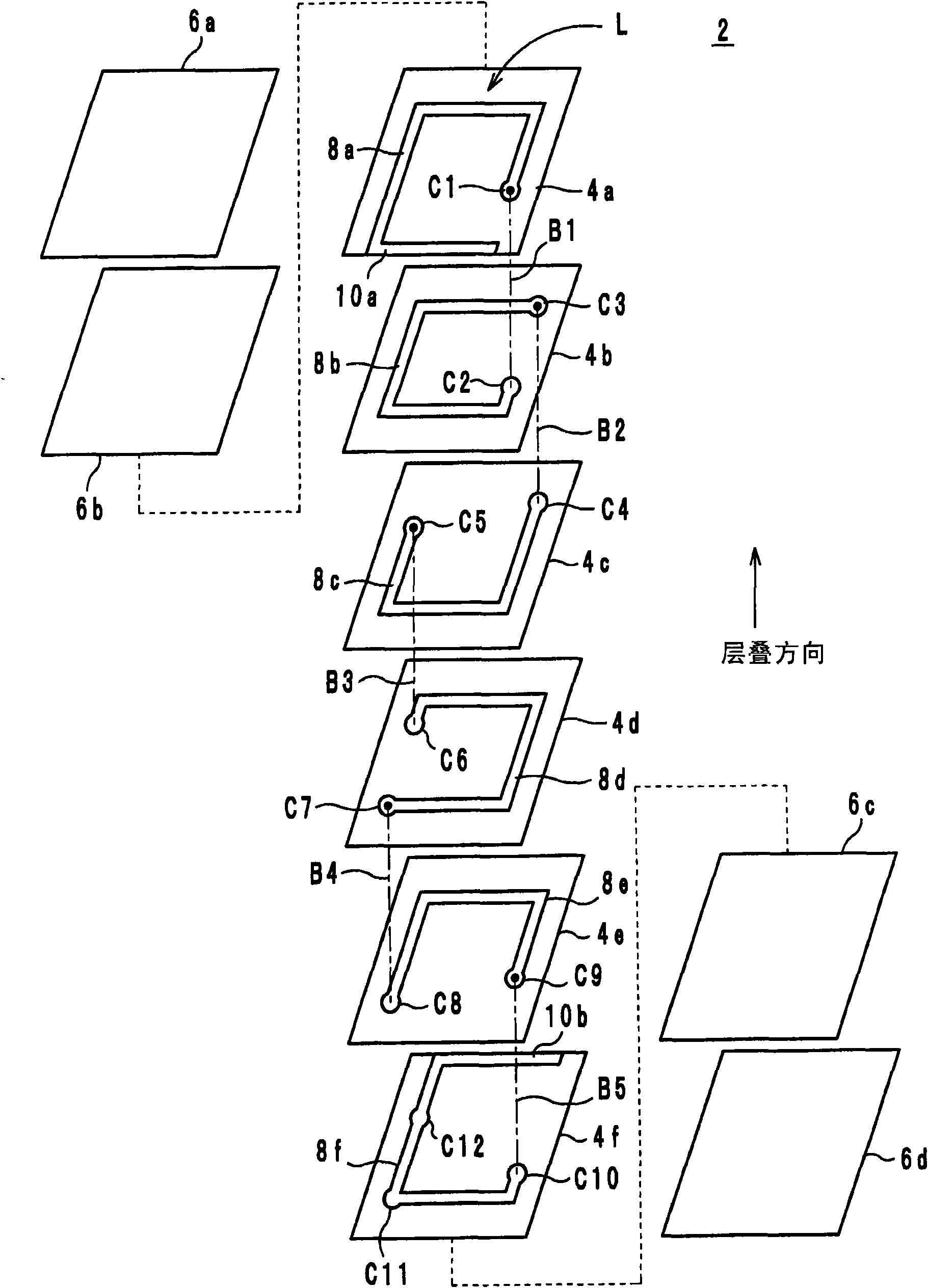
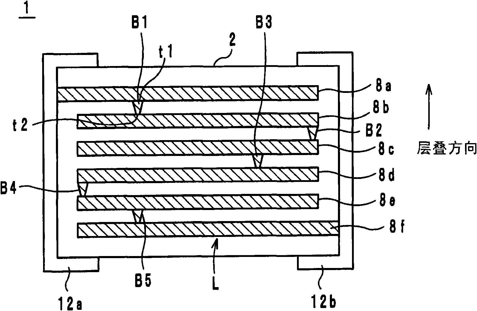
[0049] Next, a multilayer electronic component and its manufacturing method according to one embodiment of the present invention will be described. This multilayer electronic component can be used for an inductor, an impedance element (impedor), and an LC filter, for example. figure 1 It is an external perspective view of the multilayer electronic component 1 . figure 2 It is an exploded perspective view of the laminated body 2 . image 3 It is a perspective view looking at the multilayer electronic component 1 from the side direction. Hereinafter, the direction in which ceramic green sheets are laminated when forming the laminated electronic component 1 is defined as the lamination direction.

[0050] (About the structure of laminated electronic components)

[0051] Such as figure 1 As shown, the laminated electronic component 1 includes: a cuboid laminated body 2 containing a coil L inside; and two external electrodes 12a, 12b formed on opposite sides (surfaces) of th...


PUM


Abstract

The present invention provides a stacking type electronic component capable of preventing disconnection between a through-hole conductor and a coil electrode, and a method for manufacturing the same. A coil is composed of a plurality of coil electrodes (8). A stacking body (2) is formed by stacking a plurality of magnetic body layers (4) and a plurality of coil electrodes (8). A contact part (C) is connected to the a plurality of coil electrodes (8) and has a shape that one end area is larger than the other end area. An external electrode is formed on the surface of a stacking body and is connected with the coil. A coil electrode (8a) is longer than a coil electrode (8f). the coil electrode (8a) is connected with the end part of a contact part (B1).

Description

technical field [0001] The present invention relates to a laminated electronic component and its manufacturing method, and relates to a laminated electronic component formed by laminating insulating layers and coil electrodes and its manufacturing method. Background technique [0002] Next, the configuration of a conventional multilayer electronic component incorporating a coil will be described with reference to the drawings. Figure 9 It is a perspective view of a conventional multilayer electronic component 100 . Figure 10 It is an exploded perspective view of a laminated body 102 of a conventional laminated electronic component 100 . [0003] Such as Figure 9 As shown, the multilayer electronic component 100 includes: a rectangular parallelepiped multilayer body 102 including a coil inside; and two external electrodes 112a and 112b formed on opposite side surfaces of the multilayer body 102 . [0004] The laminated body 102 is formed by laminating a plurality of coil ...

Claims


Application Information

Patent Timeline
Patent Type & Authority Applications(China)
IPC IPC(8): H01F17/00H01F27/28H01F27/32
Inventor 前田智之
Owner MURATA MFG CO LTD
Why Eureka
Try Eureka