
Anode and battery

an anode and battery technology, applied in the field of anode and battery, can solve the problems of achieve the effects of reducing cycle characteristics and safety, high performance, and increasing electric power consumption of batteries

Active Publication Date: 2009-04-16
MURATA MFG CO LTD
View PDF4 Cites 25 Cited by
  • Summary
  • Abstract
  • Description
  • Claims
  • Application Information

AI Technical Summary

Benefits of technology

[0010]In recent years, in the portable electronic devices, the high performance and the multi functions tend to be increasingly developed and thus, electric power consumption thereof tends be increased. Accordingly, there is a tendency that charge and discharge of the secondary battery used for the portable electronic devices are frequently repeated, and thus the cycle characteristics and the safety are easily lowered. Therefore, further improvement of the cycle characteristics and the safety of the secondary battery is aspired.
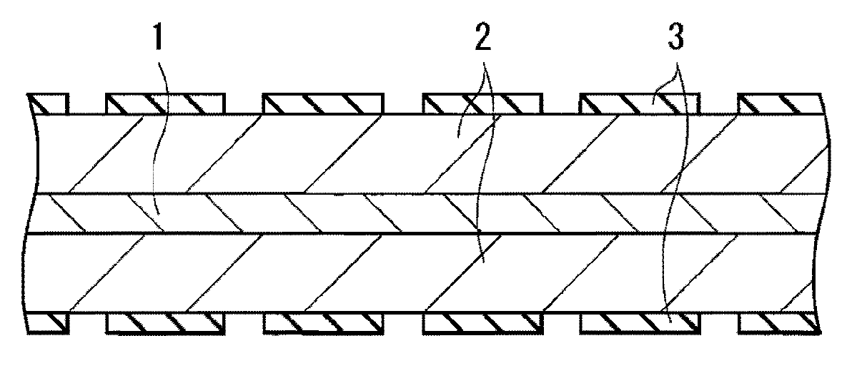
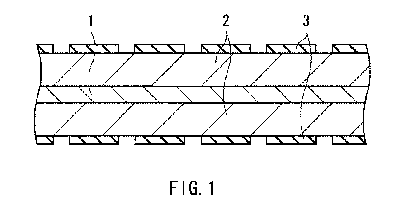
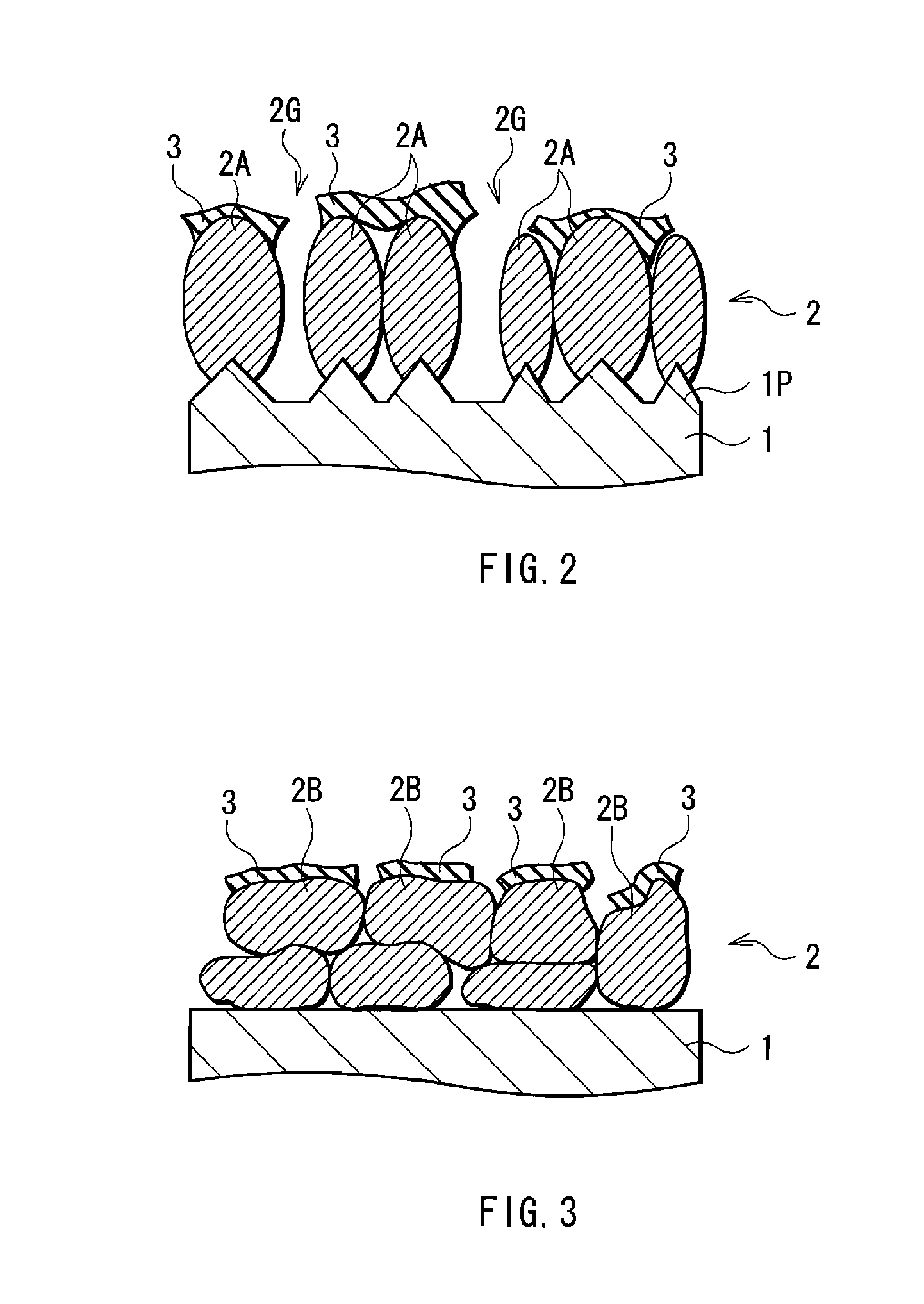
[0013]According to the anode of the embodiment of the invention, the anode has the insulative coat divided into a plurality of portions on the anode active material layer. Therefore, in the case where the anode is used for an electrochemical device such as a battery, the insulation property of the coat prevents internal short circuit, and the plurality of portions of the coat prevent separation of the anode active material layer and decomposition of the electrolytic solution. Further, even when short circuit occurs, heat generation is prevented by heat absorption characteristics of the coat. Thereby, according to the battery including the anode of the invention, superior cycle characteristics and safety are obtained.

Problems solved by technology

In recent years, in the portable electronic devices, the high performance and the multi functions tend to be increasingly developed and thus, electric power consumption thereof tends be increased.

Method used


Image

  • Anode and battery
  • Anode and battery
  • Anode and battery

Examples


example 1-1

[0142]To examine the cycle characteristics, the coin-type secondary battery shown in FIG. 14 was fabricated by the following procedure. The secondary battery was fabricated as a lithium ion secondary battery in which the capacity of an anode 72 was expressed based on insertion and extraction of lithium.

[0143]First, a cathode 71 was formed. First, lithium carbonate (Li2CO3) and cobalt carbonate (CoCO3) were mixed at a molar ratio of 0.5:1. After that, the mixture was fired in the air at 900 deg C. for 5 hours. Thereby, lithium cobalt complex oxide (LiCoO2) was obtained. Subsequently, 91 parts by weight of the lithium cobalt complex oxide as a cathode active material, 6 parts by weight of graphite as an electrical conductor, and 3 parts by weight of polyvinylidene fluoride as a binder were mixed to obtain a cathode mixture. After that, the cathode mixture was dispersed in N-methyl-2-pyrrolidone (NMP) to obtain paste slurry. Subsequently, a single face of a cathode current collector 71...

examples 1-2 to 1-11

[0150]A procedure was performed in the same manner as that of Example 1-1, except that the unit weight was changed to 0.02 mg / cm2 (Example 1-2), 0.04 mg / cm2 (Example 1-3), 0.06 mg / cm2 (Example 1-4), 0.08 mg / cm2 (Example 1-5), 0.1 mg / cm2 (Example 1-6), 0.2 mg / cm2 (Example 1-7), 0.4 mg / cm2 (Example 1-8), 0.6 mg / cm2 (Example 1-9), 0.8 mg / cm2 (Example 1-10), or 1 mg / cm2 (Example 1-11). The area ratio S2 / S1 was 0.4 in Example 1-2, 0.8 in Example 1-3, and 0.9 in Examples 1-4 to 1-11.

examples 2-1 and 2-2

[0158]A procedure was performed in the same manner as that of Example 1-6, except that a plating solution was prepared by using zirconium nitrate or titanium nitrate instead of aluminum nitrate, and zirconium hydroxide (Example 2-1) or titanium hydroxide (Example 2-2) instead of aluminum hydroxide was precipitated to form the coats 72C and 22C.


PUM


Abstract

A battery capable of obtaining superior cycle characteristics and safety is provided. The battery includes a cathode, an anode, and an electrolytic solution. The electrolytic solution is impregnated in a separator provided between the cathode and the anode. The anode has an insulative coat on an anode active material layer provided on an anode current collector. The coat contains an insulating material such as a meal hydroxide and a metal oxide. The coat is in a form of plate divided into a plurality of portions. The insulation property of the coat prevents internal short circuit. A plurality of portions of the coat prevent separation of the anode active material layer and decomposition of the electrolytic solution. Further, even when short circuit occurs, heat generation is prevented by heat absorption characteristics of the coat.

Description

CROSS REFERENCES TO RELATED APPLICATIONS[0001]The present invention contains subject matter related to Japanese Patent Application JP 2007-268348 filed in the Japanese Patent Office on Oct. 15, 2007, the entire contents of which being incorporated herein by reference.BACKGROUND OF THE INVENTION[0002]1. Field of the Invention[0003]The present invention relates to an anode having an anode active material layer on an anode current collector and a battery including the same.[0004]2. Description of the Related Art[0005]In recent years, portable electronic devices such as combination cameras (videotape recorder), mobile phones, and notebook personal computers have been widely used, and it is strongly demanded to reduce their size and weight and to achieve their long life. Accordingly, as a power source, a battery, in particular a light-weight secondary batter capable of providing a high energy density has been developed.[0006]Specially, a secondary battery using insertion and extraction o...

Claims


Application Information

Patent Timeline
IPC IPC(8): H01M4/02H01M4/06H01M4/12H01M4/13H01M4/133H01M4/134H01M4/139H01M6/16H01M10/052H01M10/0566
CPCH01M4/02H01M4/366H01M4/48H01M4/62H01M10/4235H01M2004/027Y02E60/122H01M4/134H01M10/0525H01M2004/021Y02E60/10H01M10/05H01M4/386H01M2220/00
Inventor FUJII, TAKAYUKIKAWASE, KENICHINAKAI, HIDEKIIMOTO, RIKAKOYAMAMOTO, KENSUKE
Owner MURATA MFG CO LTD
Learn More