Non-contact energy transmission type ultrasonic machining device

An energy transmission and ultrasonic processing technology, applied in the field of ultrasonic assisted processing, can solve the problems of high tool speed, inability to realize automatic tool change, and rapid wear of carbon brushes, so as to improve the power transmission efficiency, meet the needs of automatic tool change, Detachable and convenient effect

Inactive Publication Date: 2014-08-27
张增英
View PDF6 Cites 29 Cited by
  • Summary
  • Abstract
  • Description
  • Claims
  • Application Information

AI Technical Summary

Problems solved by technology

[0004] Traditional ultrasonic-assisted machining transmits energy through the frictional contact of carbon brushes and conductive slip rings to supply power to the transducers. Therefore, carbon brushes wear quickly, heat is large, wires are exposed, carbon deposits are easy to ignite, and the tool speed cannot be too high. Problems such as automatic tool change cannot be realized

Method used


Image

  • Non-contact energy transmission type ultrasonic machining device
  • Non-contact energy transmission type ultrasonic machining device
  • Non-contact energy transmission type ultrasonic machining device

Examples


Embodiment

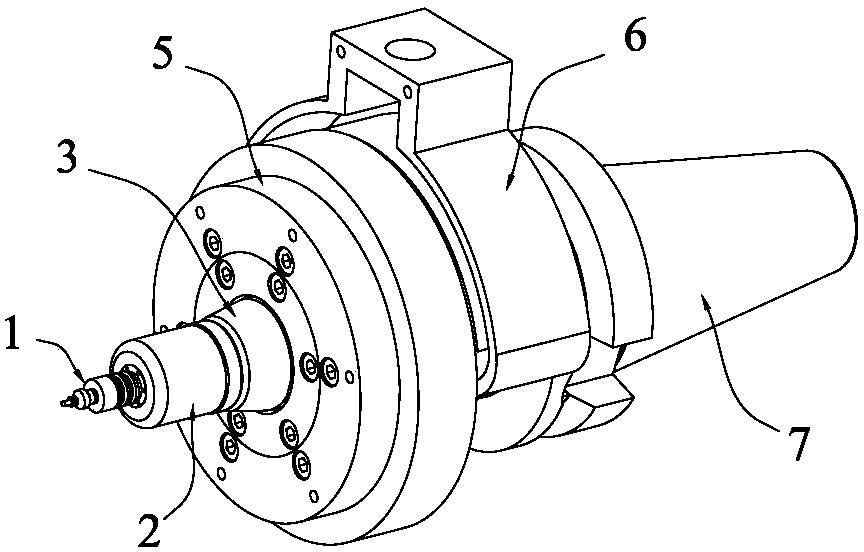
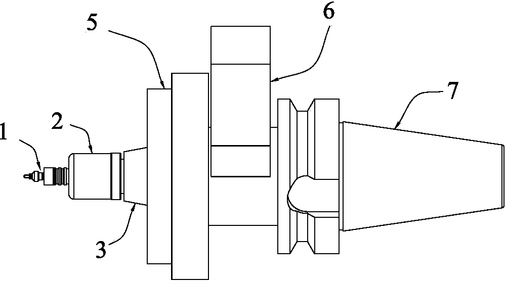
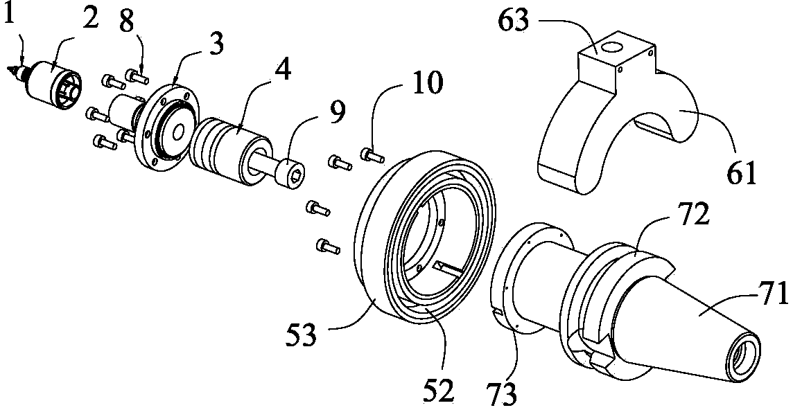
[0020] Example: see figure 1 , figure 2 , image 3 with Figure 4 , a non-contact energy transmission ultrasonic processing device provided by the present invention, which includes a grinding head 1, a horn 2, a front cover 3, a piezoelectric ceramic 4, a secondary magnetic loop coil 5, and a primary magnetic loop coil 6 and the handle 7, preferably, the total length of the non-contact energy transmission ultrasonic machining device of the present invention is 204-205 mm, preferably 204.05 mm.

[0021] see Figure 4 One end of the handle 7 is tapered to form a clamping portion 71, the middle radially protrudes to form a positioning portion 72, and the other end is provided with a flange to form an assembly portion 73. The center position of the end surface of the assembly portion 73 is There is an assembly recess 74, the front cover 3 is fixed on the inner side of the assembly part 73 by six bolts 8, and the opening of the assembly recess 74 is closed, and the piezoelectr...


PUM

PropertyMeasurementUnit
diameteraaaaaaaaaa
diameteraaaaaaaaaa
lengthaaaaaaaaaa

Abstract

The invention discloses a non-contact energy transmission type ultrasonic machining device. The non-contact energy transmission type ultrasonic machining device comprises a grinding head, an amplitude-change rod, a front cover plate, piezoelectric ceramic, secondary magnetic ring coil, a primary magnetic ring coil and a tool handle. The grinding head, the amplitude-change rod, the front cover plate and the tool handle are sequentially connected, the piezoelectric ceramic is arranged in a concave assembly position of the tool handle, the secondary magnetic ring coil is fixed to the front cover plate, the primary magnetic ring coil is arranged on a mechanical arm of an ultrasonic machine, and gap is formed between the secondary magnetic ring coil and the primary magnetic ring coil. The non-contact energy transmission type ultrasonic machining device is ingenious and reasonable in structural design; because of the non-contact energy transmission structure design, not only is non-contact high-efficiency transmission of electric energy achieved, but also the problem of traditional slip ring abrasion in ultrasonic machining is solved, the heat generation phenomenon caused by contact friction is avoided, the rotation speed of a spindle is increased without limitations, and meanwhile the automatic tool changing requirement of a machining center can be met; moreover, because no exposed conductors exist, electric energy transmission is not influenced by environments, and the non-contact energy transmission type ultrasonic machining device is good in working stability, safe, reliable, capable of keeping work for a long time and high in working efficiency.

Description

technical field [0001] The invention relates to the technical field of ultrasonic assisted processing, in particular to a non-contact energy transmission type ultrasonic processing device. Background technique [0002] Ultrasonic-assisted machining, as an effective composite machining method for machining difficult-to-machine materials, has been widely used in aerospace, precision instruments, optics, and medical fields. [0003] In ultrasonic assisted machining, the transducer vibrates mechanically at ultrasonic frequency and rotates at high speed with the processing tool. How to transmit the high-frequency ultrasonic electrical signal to the transducer of the high-speed rotating ultrasonic vibration unit is a prerequisite and difficulty for realizing ultrasonic-assisted machining. [0004] Traditional ultrasonic-assisted machining transmits energy through the frictional contact of carbon brushes and conductive slip rings to supply power to the transducers. Therefore, carb...

Claims


Application Information

Patent Timeline
Patent Type & Authority Applications(China)
IPC IPC(8): B24B1/04
CPCB24B1/04
Inventor 张增英
Owner 张增英
Why Eureka
Try Eureka