Mechanical exercycle
An exercise bike and mechanical technology, applied to motor vehicles, bicycles, vehicle parts, etc., can solve the problems of unsatisfactory fitness effect, lack of interest and entertainment of ordinary baby carriages, etc., achieve simple structure, improve flexibility, and improve sports interest Effect
- Summary
- Abstract
- Description
- Claims
- Application Information
AI Technical Summary
Problems solved by technology
Method used
Image
Examples
example 1
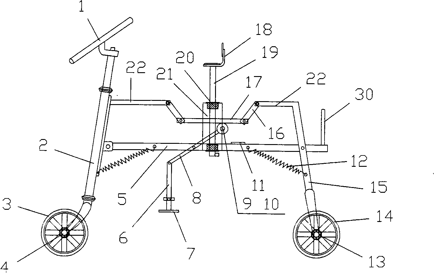
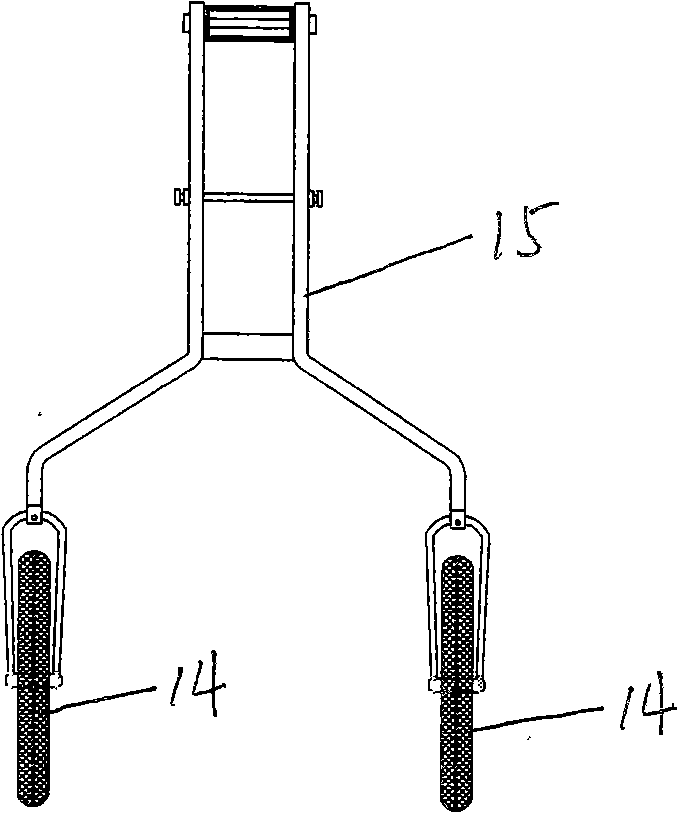
[0021] Example 1: see figure 1 , one of structure of the present invention, comprises girder 5, front and rear fork 2 and 15 and front and rear wheels 3 and 14 that are contained in girder 5 front and rear ends, wherein rear fork 15 is equipped with left and right rear wheels 14 (referring to figure 2 ), the front fork 2 is also equipped with a faucet 1, especially the upper middle parts of the front and rear forks 2 and 15 are hinged with the front and rear ends of the main beam 5, and a return spring 12 is installed between the main beam 5 and the front and rear forks The tail end of the main beam 5 is provided with a handle 30 for easy handling; the front and rear forks 2 and 15 are respectively designed with extension rods 22 inwardly, and the outer ends of the two extension rods 22 are respectively connected to a connecting rod 16 and two connecting rods 16 The other end of the other end is respectively hinged with the two ends of a suspension beam 17; a cylindrical guid...
example 2
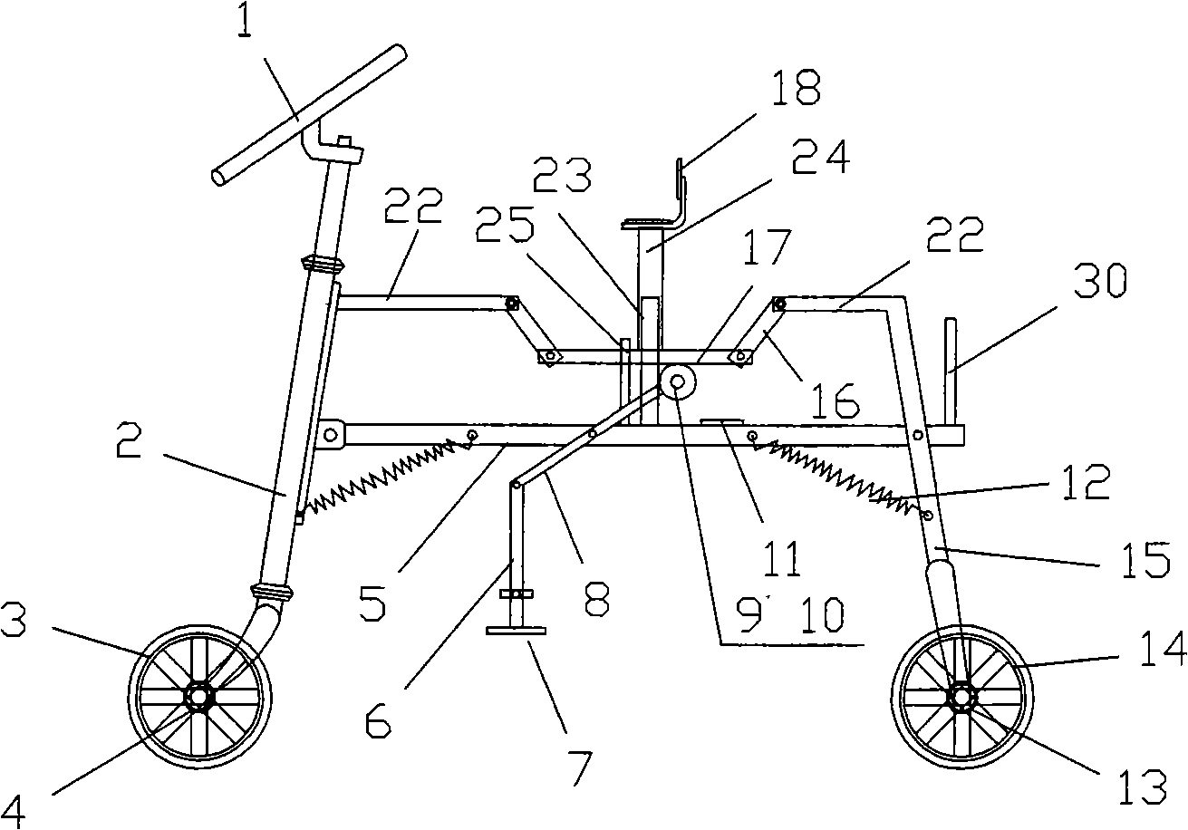
[0023] Example 2: see image 3 , the second structure of the present invention, the basic structure is the same as example 1, the difference is: the cylindrical guide seat 21 fixed on the main beam 5 in example 1 is changed into column guide seat 23, and the sliding rod 19 in example 1 Sliding sleeve 24 is changed into, simultaneously for preventing suspension beam 17 from lifting too high, a " door " shape limit frame 25 is installed next to guide seat 23 on main beam 5 , and suspension beam 17 is worn on limit frame 25 Among them, constitute the second structure of the present invention. Its working principle is the same as example 1.
example 3
[0024] Example 3: see Figure 4 , the third structure of the present invention, the basic structure is the same as Example 1, the difference is: the front and rear fork extension rods 22 are changed to be inclined, and the two connecting rods 16 connected with the two extension rods 22 are canceled; and the original suspension beam is changed into a chute Type suspension beam 26 (promptly open system chute in suspension beam 26), adopt two slide shafts 27 to be contained in two extension rods 22 outer ends of front and rear forks respectively, and slide shaft 37 is contained in the chute type suspension beam 26 Promptly constitute three of the structure of the present invention in the chute. Its working principle is basically the same as example 1, the difference is that since the connecting rod 16 is omitted, the chute-type suspension beam 26 directly drives the two extension rods 22 to move inward or outward so as to drive the front and rear forks 2 and 15 to open or close t...
PUM
 Abstract
Description
Claims
Application Information
 - R&D
- Intellectual Property
- Life Sciences
- Materials
- Tech Scout
- Unparalleled Data Quality
- Higher Quality Content
- 60% Fewer Hallucinations
Browse by: Latest US Patents, China's latest patents, Technical Efficacy Thesaurus, Application Domain, Technology Topic, Popular Technical Reports.
© 2025 PatSnap. All rights reserved.Legal|Privacy policy|Modern Slavery Act Transparency Statement|Sitemap|About US| Contact US: help@patsnap.com


