Multi-antenna transmission device, multi-antenna reception device, multi-antenna transmission method, multi-antenna reception method, terminal device, and base station device
A technology of a transmitting device and a terminal device is applied in the fields of multi-antenna transmitting device, multi-antenna receiving device, multi-antenna transmitting, multi-antenna receiving, terminal device and base station device, which can solve the problem of reducing the scale of MLD operation circuit and achieve a simplified structure Effect
- Summary
- Abstract
- Description
- Claims
- Application Information
AI Technical Summary
Problems solved by technology
Method used
Image
Examples
Embodiment approach 1
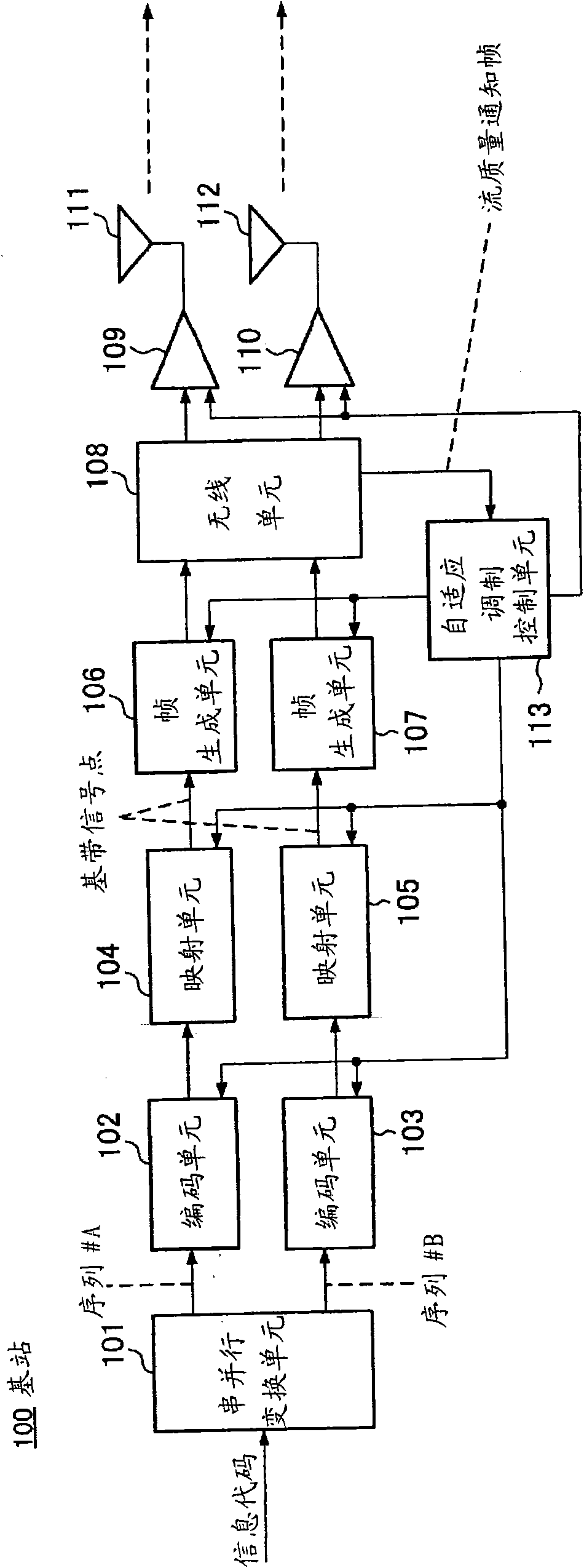
[0116] In this embodiment, a MIMO-AMC reception device will be described. That is, in the present embodiment, in the MIMO-AMC system, the reception device detects the spatially multiplexed signal using the MLD. In this embodiment, a configuration in which a terminal performs signal detection by MLD will be described. The terminal according to the present embodiment is provided with an MLD computing device corresponding to a combination of modulation schemes applied to a MIMO stream, and performs detection of a spatially multiplexed signal by MLD in a MIMO-AMC system.
[0117] Figure 5 The structure of the terminal of this embodiment is shown. In this embodiment, the number of MIMO spatial multiplexing streams is 2, and QPSK (Quadrature Phase Shift Keying: Quadrature Phase Shift Keying) and 16QAM (Quadrature Amplitude Modulation: Quadrature Amplitude Modulation) modulation methods are used as the modulation method Take this as an example.
[0118] Below, refer to Figure ...
Embodiment approach 2
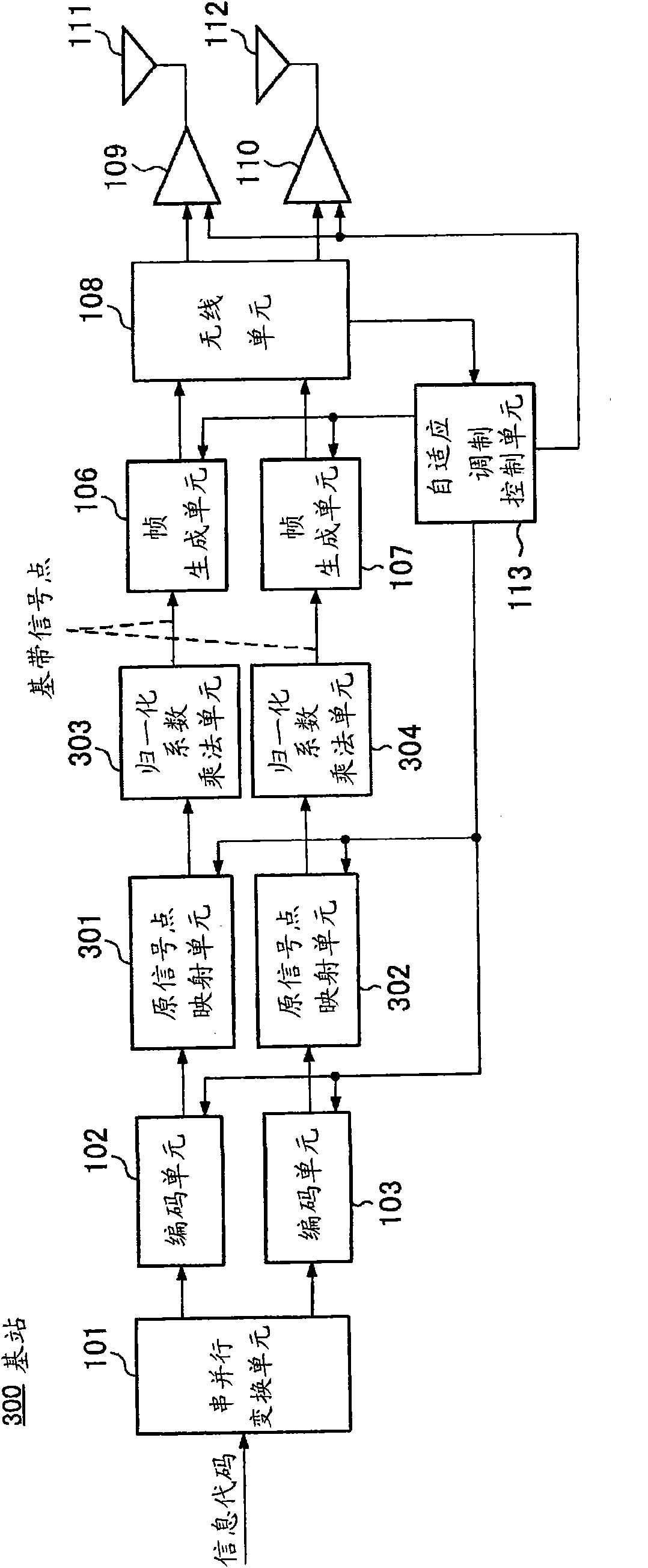
[0144] In this embodiment, an MLD computing device corresponding to the MIMO-AMC system is configured in a relatively simple manner. In the present embodiment, the signal point of the modulation method applied to the MIMO stream in the base station is commonized among the modulation methods, thereby simplifying the MID calculation device in the receiving device.
[0145] One form of the multi-antenna transmission device according to the present embodiment adopts a configuration including: a mapping unit for mapping data transmitted from different antennas in MIMO spatial multiplexing transmission to a signal common among the respective modulation schemes point; and a sending unit, configured to perform MIMO spatial multiplexing on the modulated signals obtained by mapping the same or different modulation schemes by the mapping unit.
[0146] According to this configuration, since the arrangement of mapping the channel-encoded codeword to the baseband signal point on the IQ (In...
Embodiment approach 3
[0212] In Embodiment 2, an MLD calculation device in a modulation system using the MIMO-AMC scheme is provided with a simple configuration. In Embodiment 2, by commonizing the baseband signal point arrangement of the modulation method applied to each stream, the structure of the MLD calculation performed in the receiving apparatus is commonized.
[0213] This embodiment relates to a communication system that controls transmission power of a transmission frame. When commonizing baseband signal points in a communication system that controls transmission power of transmission frames, it is necessary to commonize MLD calculations in the receiving device and commonize signal points so as not to adversely affect the communication system.
[0214] Figure 14 means to use Figure 10 The baseband signal points shown are the average power of the modulated signal. Figure 14 The (a) means to use Figure 10 The average transmission power of the pilot signal and the 16QAM modulated sig...
PUM
 Abstract
Description
Claims
Application Information
 - R&D
- Intellectual Property
- Life Sciences
- Materials
- Tech Scout
- Unparalleled Data Quality
- Higher Quality Content
- 60% Fewer Hallucinations
Browse by: Latest US Patents, China's latest patents, Technical Efficacy Thesaurus, Application Domain, Technology Topic, Popular Technical Reports.
© 2025 PatSnap. All rights reserved.Legal|Privacy policy|Modern Slavery Act Transparency Statement|Sitemap|About US| Contact US: help@patsnap.com


