
Fully automatic electric shock type insect killer for eliminating insects

A fully automatic insect zapper technology, applied in the direction of equipment that produces electric shocks, electrical components, devices that capture or kill insects, etc., can solve the problems that insects cannot be shocked by electric shocks, damaged, and easy to stick to insects, etc. Achieve good power-saving effect, excellent power-saving effect, and good insect harvesting effect

Inactive Publication Date: 2009-11-18
谢之龙
View PDF0 Cites 9 Cited by
  • Summary
  • Abstract
  • Description
  • Claims
  • Application Information

AI Technical Summary

Problems solved by technology

[0003] The high-voltage power grid is very easy to stick to the insect body, causing a short circuit in the high-voltage circuit, losing the function of the high-voltage power grid electric insect, causing subsequent insects to be unable to be shocked, and the high-voltage power grid is useless
In history, the only way to clean insects is to use artificial methods to clean insects, which is passive and backward, which seriously affects the insect killing effect of insect zappers.
[0004] The rectifier (electronic or mutual inductance) of the trap lamp is easily damaged due to the influence of voltage fluctuations
Traditionally, the outdated method of using insect-catching bags and tying them with ropes is easy to cause damage, slipping, and loss of insect-catching devices

Method used


Image

  • Fully automatic electric shock type insect killer for eliminating insects
  • Fully automatic electric shock type insect killer for eliminating insects
  • Fully automatic electric shock type insect killer for eliminating insects

Examples


Embodiment Construction

[0018] The following describes the present invention in the next step with reference to the drawings and embodiments:

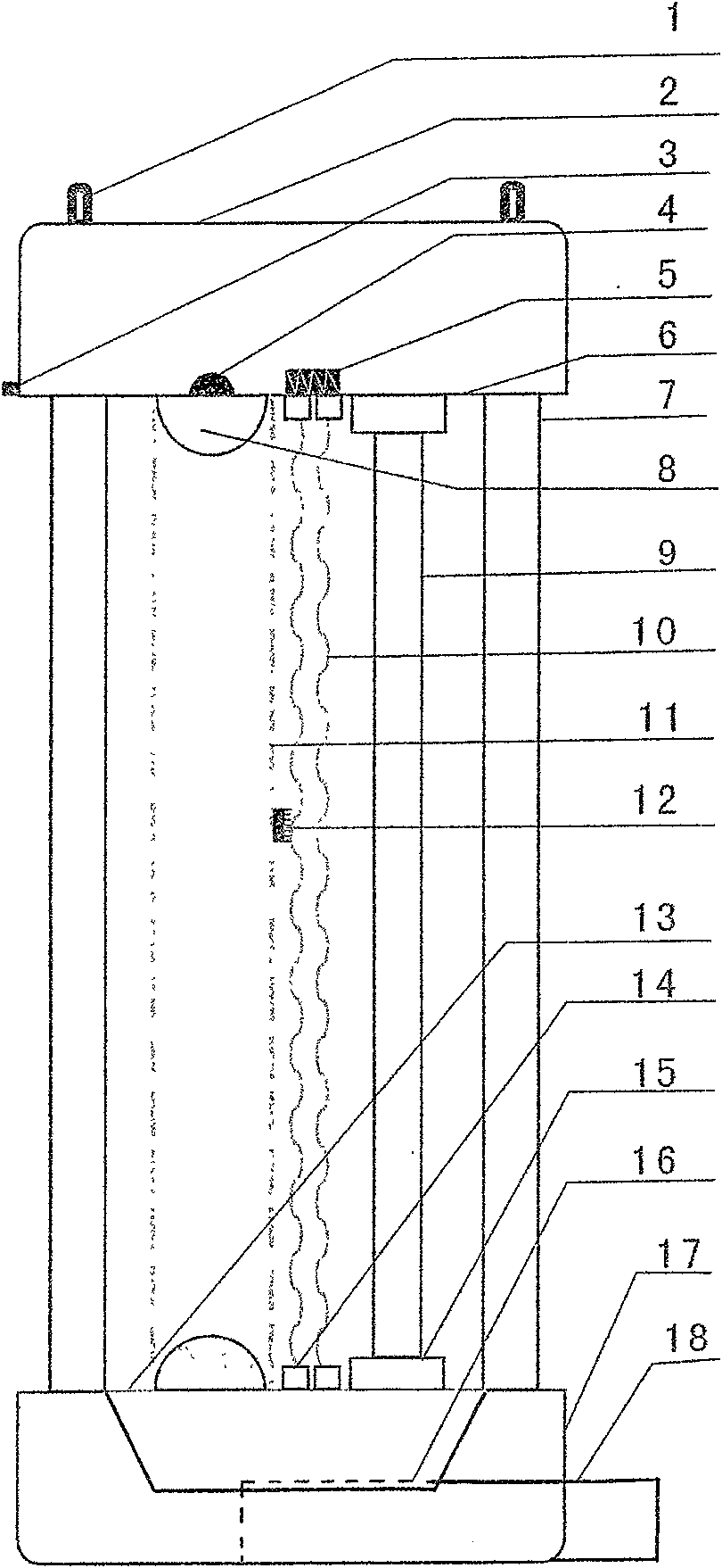
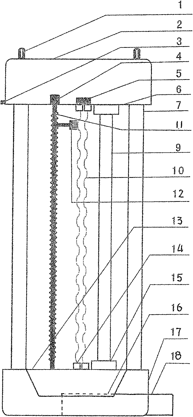
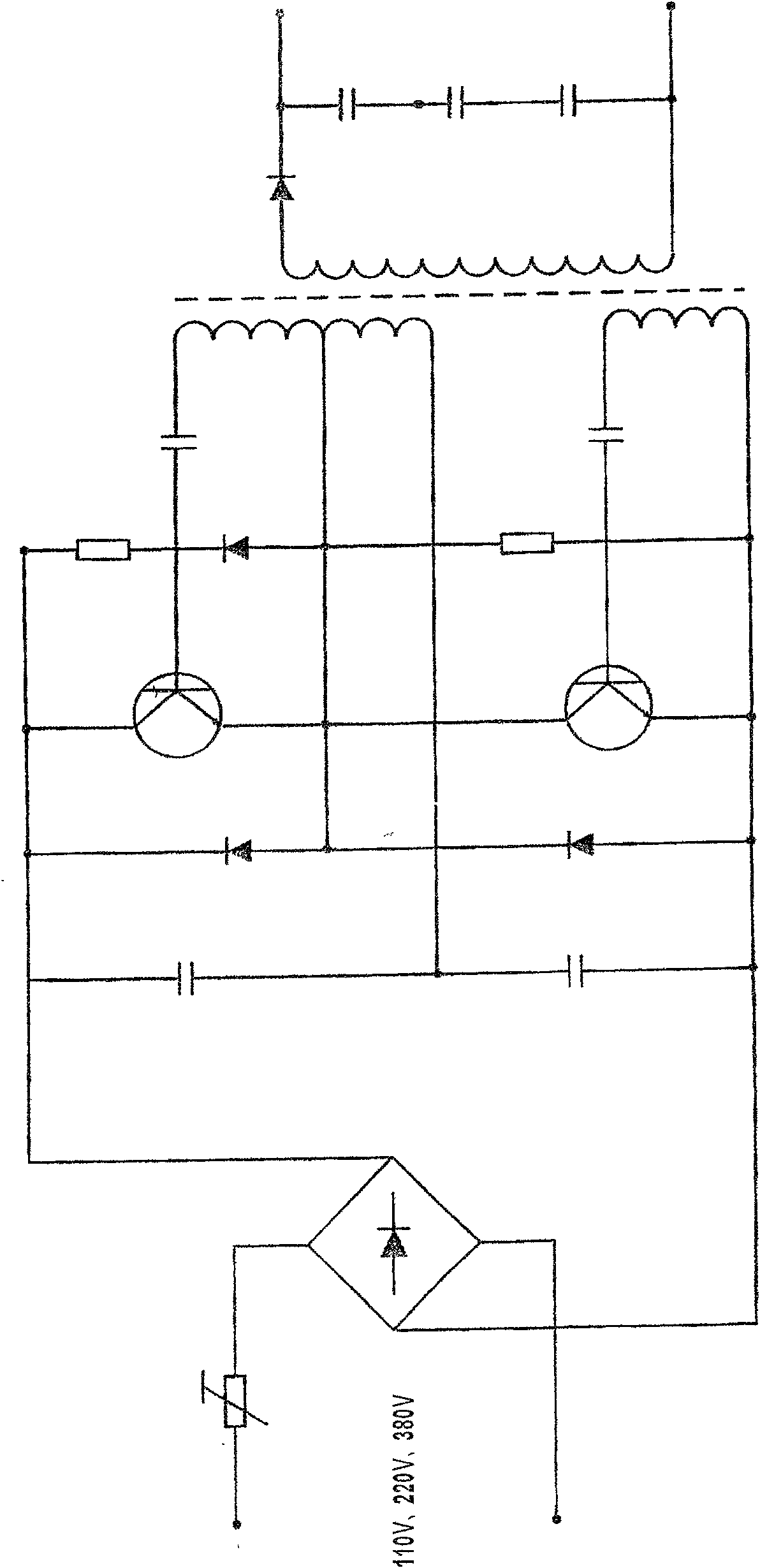
[0019] A full-automatic insect-removing electric-shock type insect exterminator, such as figure 1 As shown, it is mainly composed of the upper cover 2, the body support 7, the insect cleaner 4, 11, 12, the insect trap tube 9, the high voltage power grid 10, the control circuit 5 and the insect receiving box 18. Among them: the insect killer consists of the upper The cover 2, the support plate 6, the insect receiving funnel plate 17, the body support 7 and the high-voltage power grid 10, the insect cleaner 4, 11, 12 are composed of the motor 4, the transmission chain 11 or the belt 11 and the brush 12, and the insect trap lamp The tube 9 is composed of an inert gas lamp tube or LED light-emitting diode, a reflective material, a glass tube and a tube base 15. The high-voltage power grid 10 is composed of metal wires, which are arranged upright or horizontally fram...


PUM


Abstract

The invention relates to a fully automatic electric shock type insect killer for eliminating insects, mainly comprising an insect killer body, an insect eliminating device, an insect trapping light tube, an insect receiving case, a high-voltage electric fence and a control circuit. The insect killer comprises an upper cover, a support plate, an insect receiving funnel tray, an insect killer body bracket and the high-voltage electric fence; the insect eliminating device comprises a motor, a driving belt or a chain and a brush; and the insect trapping light tube comprises an inertia gas light tube or an LED, reflecting material, a glass tube and a tube support. The high-voltage electric fence is vertically arranged or transversely spanned on an electric fence insulating post; the insect trapping light tube is positioned near the electric fence bracket or in the middle of the electric fence bracket; the circuit board is installed on the circuit board support plate which is arranged at a position below the upper cover and above the insect trapping light tube; the bottom center of the insect receiving funnel tray is provided with an insect leaking port; the insect receiving case and the opening of the insect receiving funnel tray are in abutting joint to be in a drawer or screw socket mode without a rope for tying. The insect killer has the advantages of very good effects of killing insects, eliminating insects, receiving insects and saving electricity, and is suitable to use in both hanging and landing modes.

Description

Technical field [0001] The invention relates to an insect exterminator, especially a fully automatic insect-removing electric-shock insect exterminator, and more specifically, to a pest trap used in the fields of agriculture, forestry, horticulture, animal husbandry, urban and rural environmental sanitation and the like. Background technique [0002] Existing insecticides have the following defects while having insecticidal effects: [0003] The high-voltage power grid is very easy to stick to the sticky worms, causing short circuits in the high-voltage circuit, and losing the function of the high-voltage power grid electric worm, causing the subsequent worms to not be shocked, and the high-voltage power grid is useless. In history, the only way to clean the insects was by artificial insect removal, which was passive and backward, which seriously affected the insect extermination effect of the insect exterminator. [0004] The rectifier (electronic or mutual inductance) of the tr...

Claims


Application Information

Patent Timeline
IPC IPC(8): A01M1/22A01M1/04H05C1/00
Inventor 谢之龙
Owner 谢之龙
Learn More