Nuclear reactor alignment plate configuration

A nuclear reactor, aligning plate technology, used in reactors, nuclear engineering, nuclear power generation, etc.

Active Publication Date: 2012-12-26
WESTINGHOUSE ELECTRIC CORP
View PDF5 Cites 3 Cited by
  • Summary
  • Abstract
  • Description
  • Claims
  • Application Information

AI Technical Summary

Problems solved by technology

This is especially challenging when considering the thermal expansion and contraction that must be tolerated during a power ramp and cool down sequence where temperatures can vary between 50°F (10°C) and 580°F (304°C)

Method used


Image

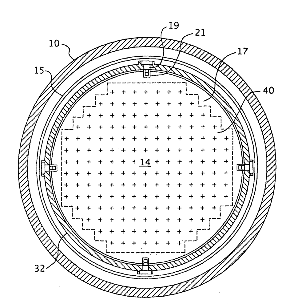
  • Nuclear reactor alignment plate configuration
  • Nuclear reactor alignment plate configuration
  • Nuclear reactor alignment plate configuration

Examples


Embodiment Construction

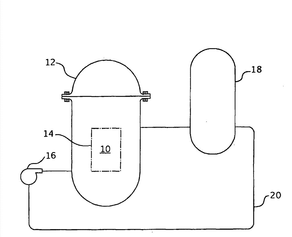
[0019] Referring now to the drawings, Figure 2 shows a simplified nuclear reactor primary system comprising a generally cylindrical reactor pressure vessel (10) having an outer shell head (12) enclosing a nuclear core (14). A liquid reactor coolant, such as water, is pumped by a pump (16) into a vessel (10) through the core (14) where thermal energy is absorbed and discharged to a heat exchanger (typically called steam generator) in which heat is transferred to a utilization circuit (not shown) such as a steam driven turbine generator. The reactor coolant is then returned to the pump (16), completing the primary loop. Typically, multiple circuits as described above are connected to a single reactor vessel (10) by reactor coolant piping (20).

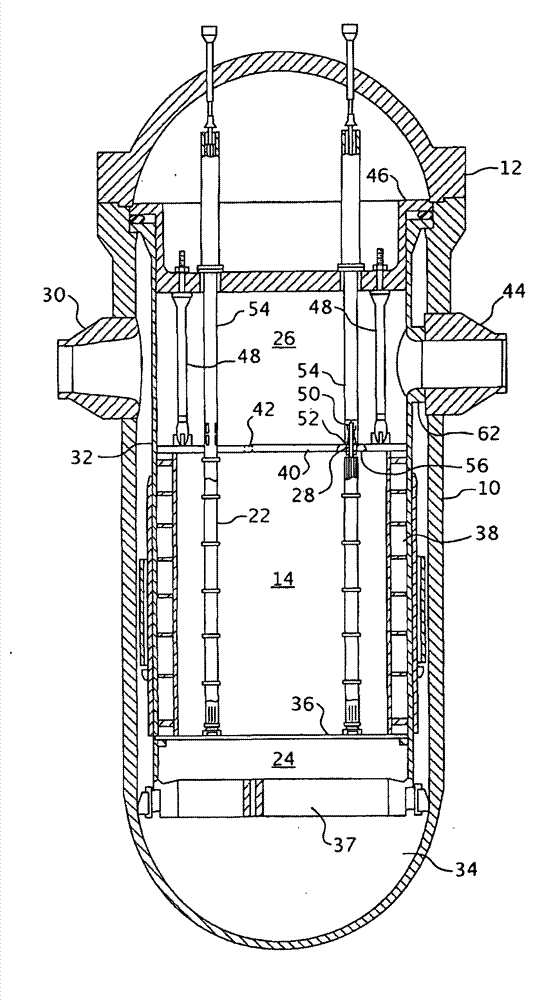
[0020] An exemplary reactor design is shown in more detail in FIG. 3 . In addition to the core (14) comprising a plurality of parallel, vertically co-extending fuel assemblies (22), for purposes of this description, other vessel interi...


PUM


Abstract

The present invention achieves the above objects by providing a pressurized water nuclear reactor comprising a pressure vessel having a core region for supporting fuel assemblies. A core barrel is removably disposed within the pressure vessel about the core region. The core shroud is disposed within the core barrel between the core barrel and the fuel assemblies. The core shroud has alignment slots that orient the core shroud to the core barrel. An upper support plate is removably disposed over the fuel assemblies and the core shroud. The upper core support plate also has alignment slots to align the upper core support plate with the core barrel and core shroud. Alignment plates are attached to the core barrel and disposed within alignment slots of the core shroud and alignment slots of the upper core support plate to maintain alignment.

Description

[0001] government interest [0002] This invention was made with government support (Contract No. DE-FC07-05ID14636 awarded by the Department of Energy). The government has certain rights in this invention. [0003] Cross References to Related Applications [0004] This application benefits from US Provisional Patent Application No. 60 / 883,072, filed January 2, 2007. technical field [0005] The present invention relates generally to nuclear reactor internals, and more particularly to apparatus for maintaining alignment of nuclear reactor internals while allowing thermal growth. Background technique [0006] The primary side of a water-cooled nuclear reactor power generation system under pressure includes a closed loop that is isolated from, and in heat exchange relationship with, a secondary side for generating useful energy. The primary side includes: the reactor vessel enclosing the core that supports multiple fuel assemblies containing fissionable material; the primar...

Claims


Application Information

Patent Timeline
Patent Type & Authority Patents(China)
IPC IPC(8): G21C1/00
CPCG21Y2004/30G21Y2002/302G21C13/024G21C19/19G21Y2002/402Y02E30/40G21C13/04Y02E30/30G21C1/00
Inventor D·A·阿尔特曼D·R·福塞斯R·E·史密斯N·R·辛格尔顿
Owner WESTINGHOUSE ELECTRIC CORP
Why Eureka
Try Eureka