
Method and device for welding inside fillet welds of T-shaped joints through infilling-type friction-stir welding

A friction stir welding and filling technology, which is applied in welding equipment, non-electric welding equipment, metal processing equipment, etc., can solve the problems of the failure of the external pad technology, the high cost of the external pad, and the low utilization rate. Increased strength, strong versatility, and increased weld reinforcement

Inactive Publication Date: 2013-02-13
JIANGSU UNIV OF SCI & TECH
View PDF5 Cites 17 Cited by
  • Summary
  • Abstract
  • Description
  • Claims
  • Application Information

AI Technical Summary

Problems solved by technology

This method has the following defects: the cost of making the outer pad is high, the utilization rate is not high, and the excess part of the pad needs to be processed by planing and milling after welding, the process is complicated, and it is not suitable for mass production.
At the same time, for special T-joints, the method of adding pads cannot form a friction plane at the corner joints, that is, for T-joints, the process of inserting pads is invalid
In the past, the patents related to the welding method of the relatively special fillet weld T-joint were mostly concentrated on fusion welding, and friction stir welding has not yet appeared related patents due to its requirements on the welding position.

Method used


Image

  • Method and device for welding inside fillet welds of T-shaped joints through infilling-type friction-stir welding
  • Method and device for welding inside fillet welds of T-shaped joints through infilling-type friction-stir welding

Examples


Embodiment Construction

[0014] The present invention will be further described below in conjunction with the accompanying drawings.

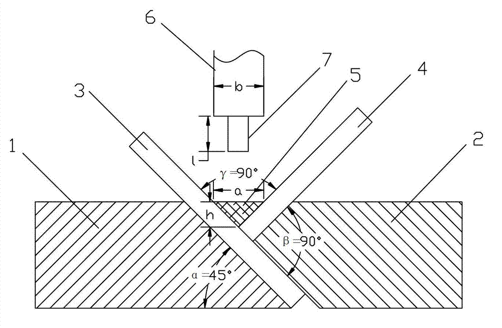
[0015] The present invention provides a friction plane for the shaft shoulder of the stirring head 6 by using specific fixtures and process auxiliary pads 5 to cooperate with the actual weldment, so as to realize the friction stir welding welding of the inner fillet weld of the T-shaped joint.

[0016] Such as figure 1 As shown, the device used to realize the welding method in the present invention includes a fixture, a stirring head 6 with a stirring needle 7, a process auxiliary pad 5 used to fill a T-joint and is homogeneous with the base material, and the fixture includes a corresponding And the first split body 1 and the second split body 2 can slide relative to each other. The side of the first split body 1 contacting the base material is at an angle of α=45° to the horizontal plane, and the angle between the two slopes of the second split body 2 contacting the b...


PUM


Abstract

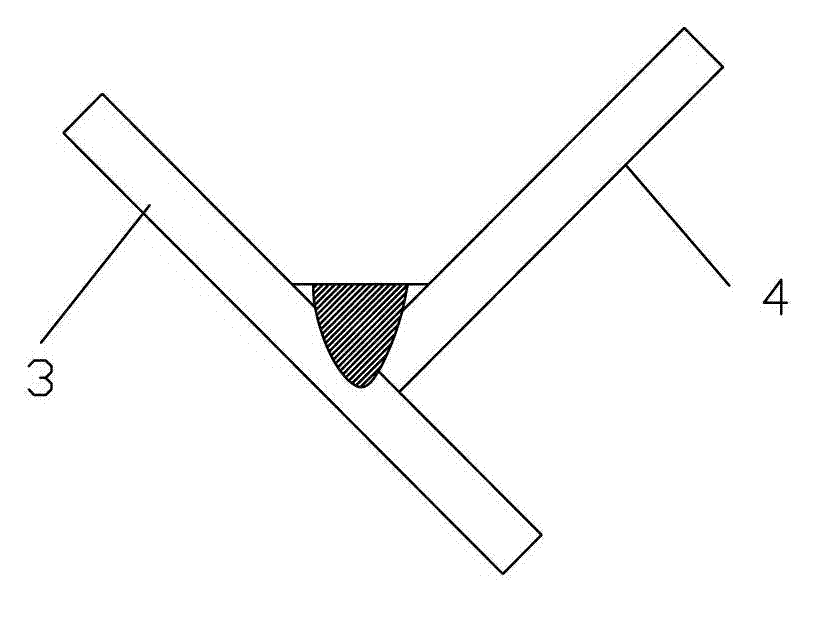
The invention discloses a method and a device for welding inside fillet welds of T-shaped joints through infilling-type friction-stir welding. The method is implemented through the steps that an inside fillet weld of a T-shaped joint is located at a flat-welding position by using a special fixture, and a process auxiliary cushion block made of a material same as that of a parent metal is embedded in the position of the inside fillet weld; a plane required by the friction of a shaft shoulder of a stir-welding head is formed at the inside fillet weld of the T-shaped joint; a weld of the T-shaped joint is heated by using the frictional heat generated by the cushion block and the shaft shoulder of the stir-welding head; and a weld of friction-stir welding is formed under the heat-engine joint action of a stirring pin. The device for implementing the method disclosed by the invention is unique in structure, low in cost and strong in universality. According to the method and the device disclosed by the invention, an effect of welding inside fillet welds of T-shaped joints through friction-stir welding can be achieved; and because the cushion block and the parent metal which are same in material are fused together, the weld reinforcement of welds can be increased, and the strength of joints is improved.

Description

technical field [0001] The invention relates to a friction stir welding method and a device for implementing the method, in particular to a filling type friction stir welding method and a device for welding an inner fillet weld of a T-shaped joint. Background technique [0002] Friction stir welding is a new type of low-temperature solid-phase joining technology, which is characterized by small changes in the microstructure of the welding heat-affected zone, relatively low residual stress, small deformation of the welded workpiece, and can be welded to heat crack sensitive materials. It is suitable for welding dissimilar materials. And the operation process is convenient, easy to realize mechanization and automation, simple equipment, low energy consumption, high efficiency, and no need to add welding wire. When welding aluminum alloys and magnesium alloys, there is no need to remove oxide films before welding, and no protective gas is required. Process safety, no pollution,...

Claims


Application Information

Patent Timeline
IPC IPC(8): B23K20/12B23K20/26
Inventor 赵勇王清曌邹家生严铿叶友利张如星肖海林周礼龙
Owner JIANGSU UNIV OF SCI & TECH
Learn More