Method for automatically welding hydraulic support structural component through welding wires with diameter being 1.6 mm

A hydraulic support and automatic welding technology, which is applied in welding equipment, arc welding equipment, manufacturing tools, etc., can solve the problems of large heat input, low welding efficiency, and large welding stress, and achieve increased weld penetration and improved welding efficiency Effect

Active Publication Date: 2017-07-04
ZHENGZHOU COAL MINING MACHINERY GRP
View PDF4 Cites 17 Cited by
  • Summary
  • Abstract
  • Description
  • Claims
  • Application Information

AI Technical Summary

Problems solved by technology

However, up to now, the welding robots used for welding hydraulic support structural parts all use solid welding wire with a diameter of 1.2mm. Although the efficiency has been greatly improved compared with manual welding, the cladding efficiency is still low due to the thinner diameter of the welding wire. , especially for production line operations, using solid welding wire with a diameter of 1.2mm for welding, and its low welding efficiency has become a bottleneck process that restricts production beats
People try to weld the above-mentioned structural parts with a welding robot using a solid welding wire with a diameter of 1.6mm, but because the solid welding wire with a diameter of 1.6mm requires high current and voltage, the heat input during welding is large, resulting in the quality and mechanical properties of the weld. In addition, the box structure of the hydraulic support structural parts makes the welding seam dense and causes a large welding stress. Therefore, welding the above structural parts using a welding robot with a diameter of 1.6mm solid welding wire has not been applied.

Method used


Image

  • Method for automatically welding hydraulic support structural component through welding wires with diameter being 1.6 mm
  • Method for automatically welding hydraulic support structural component through welding wires with diameter being 1.6 mm

Examples


Embodiment Construction

[0022] The embodiments of the present invention will be described in detail below in conjunction with the accompanying drawings. This embodiment is implemented on the premise of the technical solution of the present invention, and detailed implementation methods and specific operating procedures are provided, but the scope of protection of the present invention is not limited to the following Described embodiment.

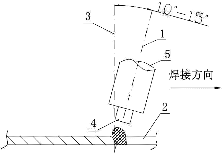
[0023] The method for automatic welding of hydraulic support structural parts using a welding wire with a diameter of 1.6mm according to the present invention comprises the following steps:

[0024] The first step is to check the part tolerance and assembly accuracy of the hydraulic support structural parts as a whole before welding. The depth tolerance of the welding groove should be controlled to be less than or equal to 2mm, the angle tolerance of the welding groove should be less than or equal to 2°, and the actual assembly of the fillet weld The gap is less th...


PUM

PropertyMeasurementUnit
diameteraaaaaaaaaa

Abstract

The invention discloses a method for automatically welding a hydraulic support structural component through welding wires with the diameter being 1.6 mm. The method includes the steps that firstly, the part tolerance and the splicing precision of the hydraulic support structural component are checked before welding, and the depth tolerance of a welding groove and the angle tolerance of the welding groove are controlled; secondly, the two sides of a weld bead are ground before welding till metallic luster appears; thirdly, all to-be-welded weld joints of the hydraulic support structural component are located at flat welding or flat fillet welding positions; fourthly, off-line programming or on-site programming teaching is conducted on a welding robot; and fifthly, multi-layer and multi-channel welding is conducted on the to-be-welded weld joints through the welding robot by means of the welding wires with the diameter being 1.6 mm in a gas shielded welding manner. According to the method, robot welding is conducted through the welding wires with the diameter being 1.6 mm, and compared with traditional welding conducted through welding wires with the diameter being 1.2 mm, under the condition that the ton cost of the welding wires is not changed and all mechanical properties of the weld joints can meet requirements, the weld penetration of the weld joints is increased, efficiency is improved by 40% or above, and the comprehensive cost of welding conducted through each ton of welding wires is saved by RMB 1500 yuan or above.

Description

technical field [0001] The invention relates to a method for automatic welding of hydraulic support structural parts by a welding robot, in particular to a method for automatic welding of hydraulic support structural parts by using a welding wire with a diameter of 1.6 mm. Background technique [0002] As the main support equipment in coal mine fully mechanized mining equipment, hydraulic support has the characteristics of large volume and weight, harsh service conditions, and many box-type welded structures. The structural parts of the hydraulic support mainly include: top beam, cover beam, base, front and rear connecting rods and other parts. These structural parts are generally box-shaped structures with a large amount of welding. Previously, the structural parts of the hydraulic support were mainly welded in the form of gas shielded welding, relying on manual multi-layer and multi-pass welding with a diameter of 1.2mm welding wire, and the welding efficiency was low. W...

Claims


Application Information

Patent Timeline
Patent Type & Authority Applications(China)
IPC IPC(8): B23K9/173B23K9/235
CPCB23K9/173B23K9/235
Inventor 王永强孟贺超李福永程相榜兰志宇孟凡炯赵旭韩振仙段青辰
Owner ZHENGZHOU COAL MINING MACHINERY GRP
Why Eureka
Try Eureka