

Three-section cover of operation table
Patent Information
- Authority / Receiving Office
- CN · China
- Patent Type
- Applications(China)
- Current Assignee / Owner
- BEIJING AEROSPACE CHANGFENG CO LTD
- Publication Date
- 2009-11-25
Smart Images
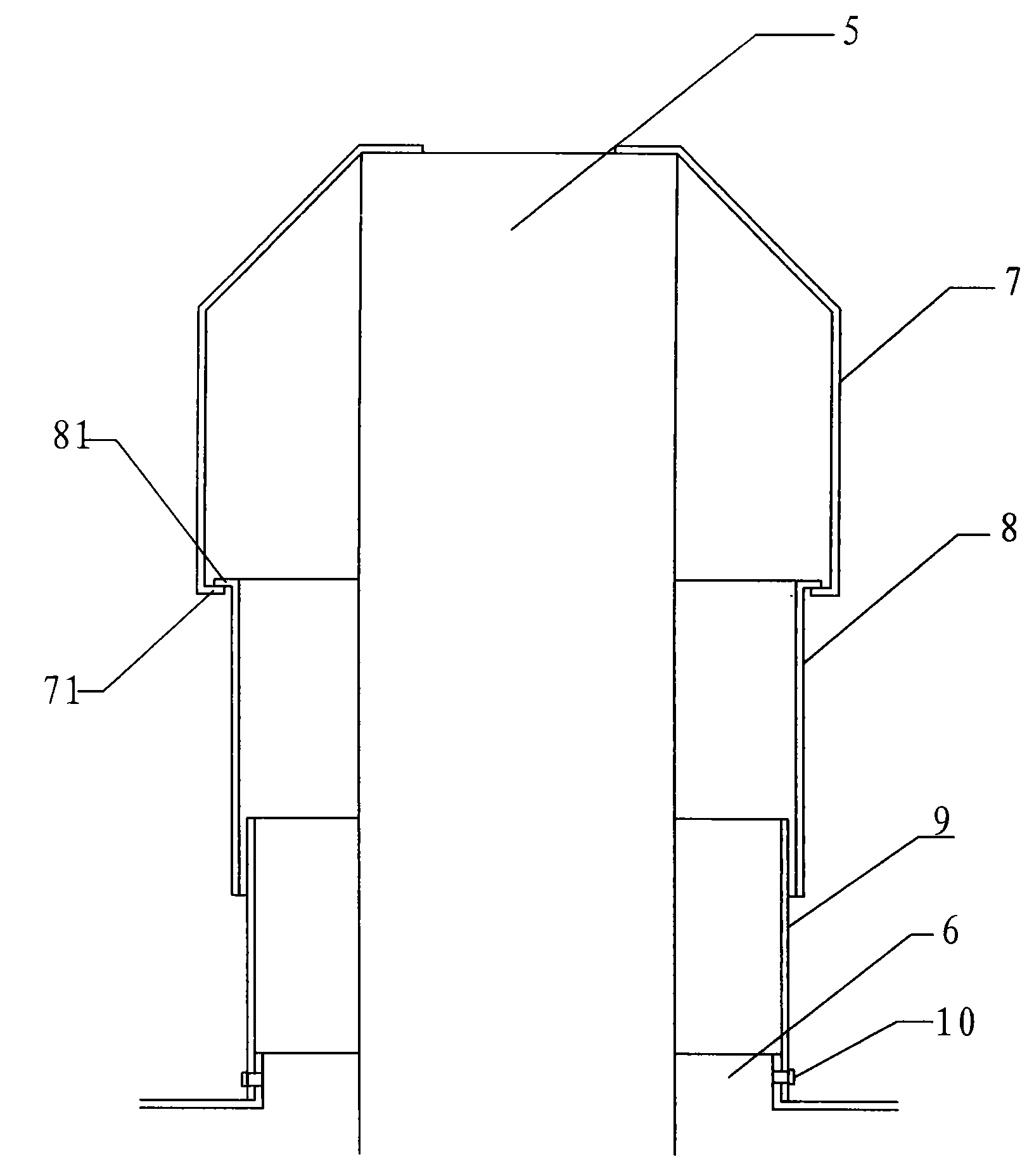
Figure 1 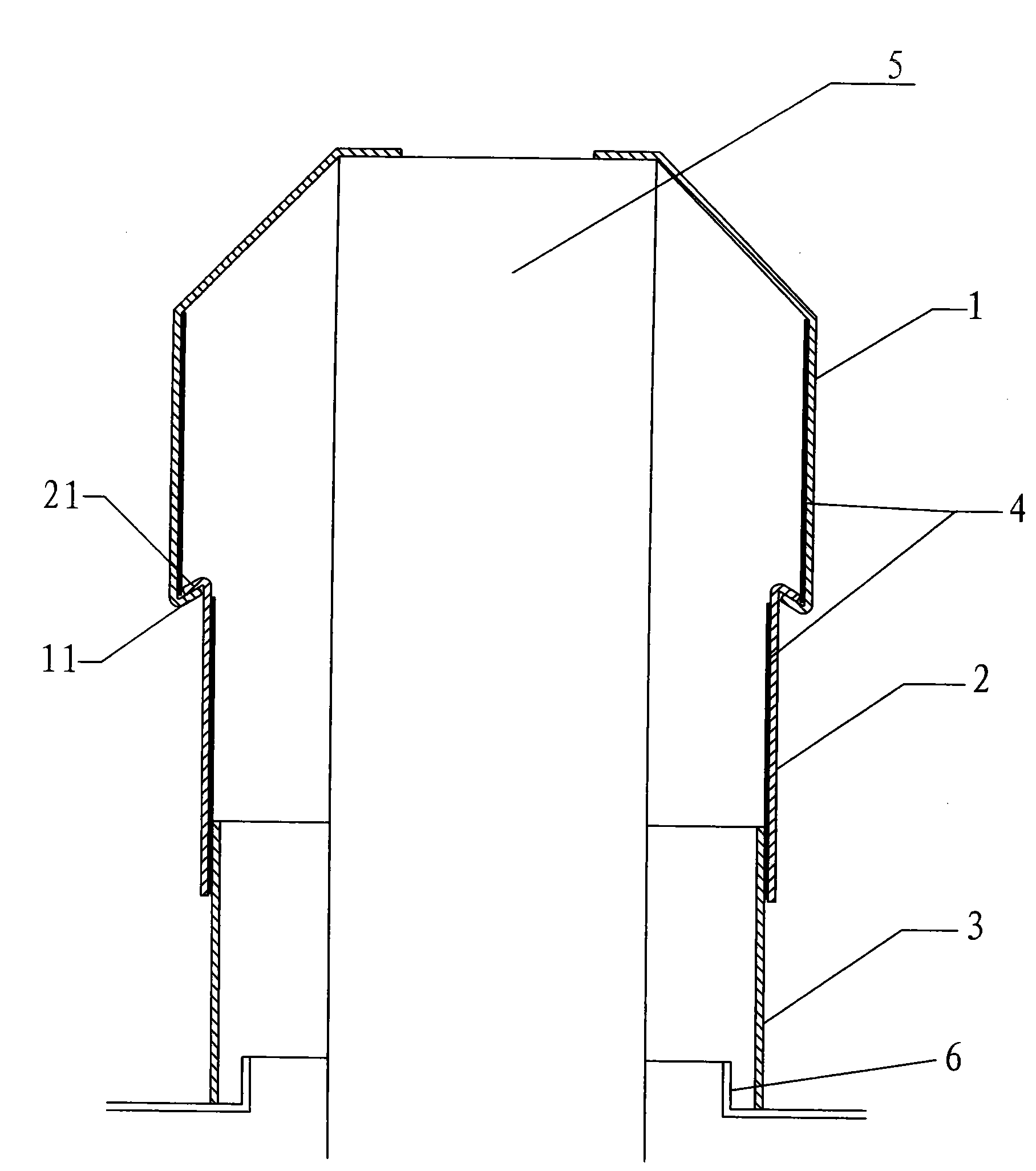
Figure 2
Abstract
Description
technical field
[0001] The invention relates to a structure of an operating bed, in particular to a structure of a three-section cover of the operating bed. Background technique
[0002] The three-section cover is a device that covers the lifting system of the operating table and moves with the movement of the lifting system. figure 1 Shown is the structure of the existing three-section cover of the operating bed, which adopts double reference positioning, the upper cover 7 is fixed on the upper end surface of the lifting system 5, and the upper end surface of the lifting system is used as the reference, and the lower cover 9 is fixed on the base by screws 10 6, with the base as a benchmark; the flanges of the lower edge 71 of the upper cover 7 and the upper edge 81 of the middle cover 8 are at right angles, and are connected to each other. Since a large error is likely to occur between the upper end surface of the lifting system and the base reference, and it is expensive ...