Railroad freight car sidebearing

A side support and carriage technology, which is used in transportation and packaging, devices for lateral relative movement between the underframe and the bogie, railway car body components, etc., and can solve the problems of restricting the vertical movement of the side support device.

Inactive Publication Date: 2009-11-25
AMSTED RAIL CO INC
View PDF0 Cites 9 Cited by
  • Summary
  • Abstract
  • Description
  • Claims
  • Application Information

AI Technical Summary

Problems solved by technology

Most existing side bearings are designed to limit the vertical movement of the side bearing

Method used


Image

  • Railroad freight car sidebearing
  • Railroad freight car sidebearing
  • Railroad freight car sidebearing

Examples


Embodiment Construction

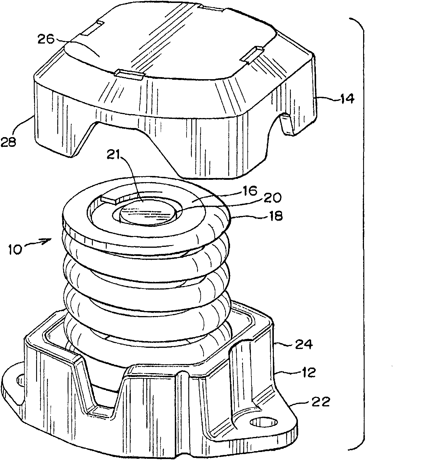
[0027] now refer to image 3 and Figure 4 , shows the side support device according to the first embodiment of the present invention. The side support 10 includes a base 12 including a base 22 and a base wall 24 extending generally vertically upward from the base 22 . Base 12 is typically a cast steel or cast iron unitary construction, but may also be fabricated or machined. The shape of the base 12 may be a user-specified circle, somewhat rectangular, somewhat oval, or rhombus.

[0028] The lid 14 is seen to include a top 26 and a wall structure 28 extending generally downwardly from the outer edge of the lid 14 . Again, cover 14 is typically of cast steel or cast iron unitary construction, but may be fabricated or machined.

[0029] The base 12 is seen to also include a base wall top stop surface 38 at the top of the base wall 24 . Likewise, the lid 14 is seen to include an inner lid stop surface 30 formed by an inner surface within the lid 14 and adjacent to and compl...


PUM


Abstract

An improved side bearing for railway cars is provided that achieves improved tracking and curving by the limitation of rock of the railway car. The side bearing comprises a base with a generally upwardly extending wall portion. A cap comprising a top section with generally downwardly extending wall portion is provided. The cap extends into or around the wall section of the base. Two coil springs are provided within the base that extend to the underside and support the cap. An elastomer spring is also provided that is located within an least of one of the coil springs.

Description

technical field [0001] The present invention relates to an improved side bearing arrangement mounted on the beam of a rail car truck to provide improved control of limiting the roll and roll characteristics of said rail car in use. Background technique [0002] In a typical rail freight train, such as figure 1 As shown, rail cars 212 and 214 are connected end-to-end by couplers 216 and 218 . Each coupler 216 and 218 is housed in a traction sill 220 and 222 of a respective respective car, along with a bumper or traction gearing (not shown). Traction sills 220 and 222 are disposed at the ends of the rail car center sills and include center plates supported in center plate bowls of rail car trucks 226 and 228 . [0003] Such as figure 2 As better shown, each exemplary car truck 226 includes a pair of side frames 230 and 232 supported on axle-wheel sets 234 and 236 . The beam 238 extends between and is supported by springs 240 mounted on the side frames 230 and 232 . The b...

Claims


Application Information

Patent Timeline
Patent Type & Authority Applications(China)
IPC IPC(8): B61F5/06
CPCB61F5/14B61F5/142
Inventor R·H·肖尔B·约翰斯通
Owner AMSTED RAIL CO INC
Why Eureka
Try Eureka