
Dehydrator

A dehydrator and head cover technology, which is applied in drying solid materials, household utensils, applications, etc., can solve the problems of wasting time, inconvenient to use, inconvenient to carry, and high in production cost, and achieves convenient portability, compact structure and low production cost. Effect

Active Publication Date: 2011-08-31
SHUANGMA PLASTIC MFG INC
View PDF1 Cites 2 Cited by
  • Summary
  • Abstract
  • Description
  • Claims
  • Application Information

AI Technical Summary

Problems solved by technology

[0002] After the fruits and vegetables are washed with water, a large amount of water remains on the surface, so when using these fruits and vegetables, the water needs to be wiped off or dried, which is a waste of time
Also useful machine dehydration now, as the patent No. 200420076012.4 the patent has announced a kind of vegetable dehydrator, and it comprises bung, dehydration bucket, rotating shaft and motor, and it mainly is to utilize the drive of motor to make dehydration bucket rotate and come the vegetables on the vegetable dehydrator. The water is turned dry, the production cost of this dehydrator is high, and it is extremely inconvenient to use and carry

Method used


Image

  • Dehydrator
  • Dehydrator

Examples


Embodiment Construction

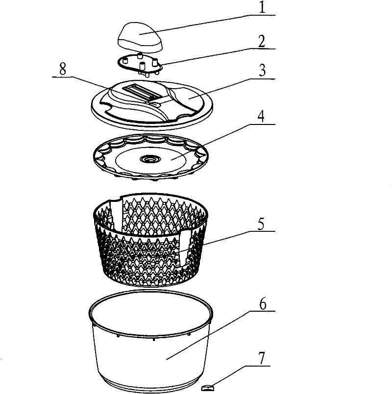
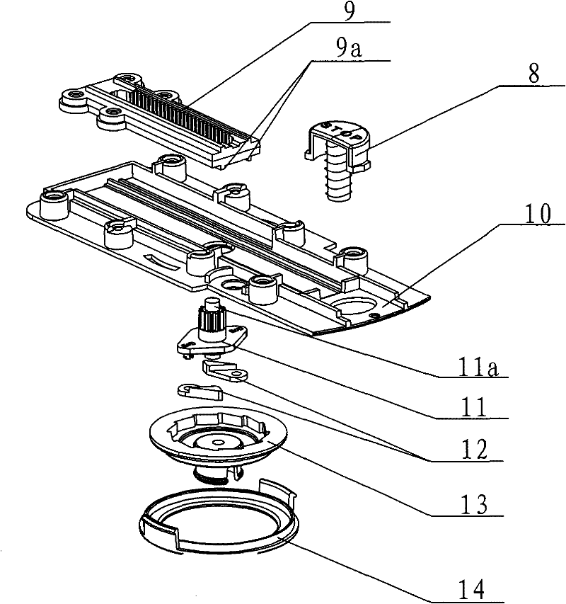
[0018] As shown in the figure, a dehydrator includes a planer cover, a wire basket 5 and a bucket body 6 . The planer head cover includes a pressing hand body, planer head cover main body 3 and fan blade 4, the pressing hand body is composed of pressing hand cover 1 and pressing hand bottom 2, pressing hand cover 1 and pressing hand bottom 2 are screwed, and the whole pressing hand body is screwed On the rack 9 of the main body 3 of the planer head cover, the upper part of the main body 3 of the planer head cover is slotted, which is conducive to the back and forth sliding of the presser body. The main body 3 of the planer head cover is provided with a fixed plate 10, which is screwed to the planer head cover On the lower surface of the main body 3, a rack 9 is set on the surface of the fixed plate 10, a slot is arranged in the middle of the rack 9, teeth are arranged on both sides of the slot, two convex strips 9a are arranged on the lower surface of the rack 9, and the convex...


PUM


Abstract

A dehydrator belongs to the dehydration apparatus technical field, comprising a planer head cover, a basket and a barrel, characterized in that the planer head cover comprises a planer head cover bodyprovided with a notch on surface, a press-hand body at upper portion of the planer head cover and a fan blade at lower portion of the planer head cover. The lower surface of the planer head cover isconnected with a fix plate fixedly which matches a rack on surface. The rack is at lower portion of the notch of the planer head cover and is provided with toothrow meshed with gears which are linkedto a rotor via actively set gear rocker. The rotor is locked with the fix plate via set rotor cover. The dehydrator is rational in design, compact in structure and completes dehydration only by pushing the press-hand lightly. Dehydration can be stopped at any time via a brake button in work process. The apparatus is low in manufacturing cost, simple in operation and easy to control and convent tocarry.

Description

technical field [0001] The invention belongs to the technical field of dehydration devices, and in particular relates to a dehydrator for vegetables and fruits. Background technique [0002] After fruits and vegetables are washed with water, a large amount of water is left on the surface, so these water contents need to be wiped off or dried when using these fruits and vegetables, which is a waste of time. Also useful machine dehydration now, as the patent No. 200420076012.4 the patent has announced a kind of vegetable dehydrator, and it comprises bung, dehydration bucket, rotating shaft and motor, and it mainly is to utilize the drive of motor to make dehydration bucket rotate and come the vegetables on the vegetable dehydrator. Moisture is dried, and the production cost of this dehydrator is high, and it is extremely inconvenient to use and carry. Contents of the invention [0003] Aiming at the problems existing in the prior art, the object of the present invention is ...

Claims


Application Information

Patent Timeline
Patent Type & Authority Patents(China)
IPC IPC(8): F26B5/08A47J43/04
Inventor 陈翠虹
Owner SHUANGMA PLASTIC MFG INC
Learn More