Self-biased phase-locked loop

一种锁相环、自偏置的技术,应用在锁相环领域,能够解决结构复杂、偏置生成器电路结构复杂等问题,达到电路结构简单、实现方便、简化电路的效果

Active Publication Date: 2009-11-25
SEMICON MFG INT (SHANGHAI) CORP
View PDF0 Cites 23 Cited by
  • Summary
  • Abstract
  • Description
  • Claims
  • Application Information

AI Technical Summary

Problems solved by technology

[0020] 3. A bias generator that generates a bias voltage from the control voltage is added to provide the input voltage of the voltage-controlled oscillator, and the circuit structure of the bias generator is also relatively complicated
[0021] Therefore, in order to meet the requirement that the damping factor of the loop is a fixed value, the existing self-biased phase-locked loop has made major changes to the basic phase-locked loop, and the structure is more complicated

Method used


Image

  • Self-biased phase-locked loop
  • Self-biased phase-locked loop
  • Self-biased phase-locked loop

Examples


Embodiment Construction

[0050] In the embodiment of the present invention, by establishing the resistance of the loop filter (that is, R in formula (1) p ) and the frequency division number of the frequency divider, the relationship between the bias current output by the voltage-controlled oscillator, the charge or discharge current output by the charge pump (that is, the I in the formula (1) p ) and the bias current output by the voltage-controlled oscillator, thereby eliminating the frequency division number and bias current to meet the requirement that the loop damping factor of the self-biased phase-locked loop maintain a fixed value.

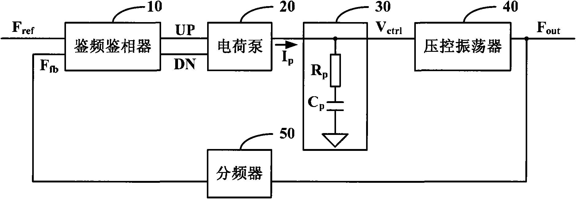
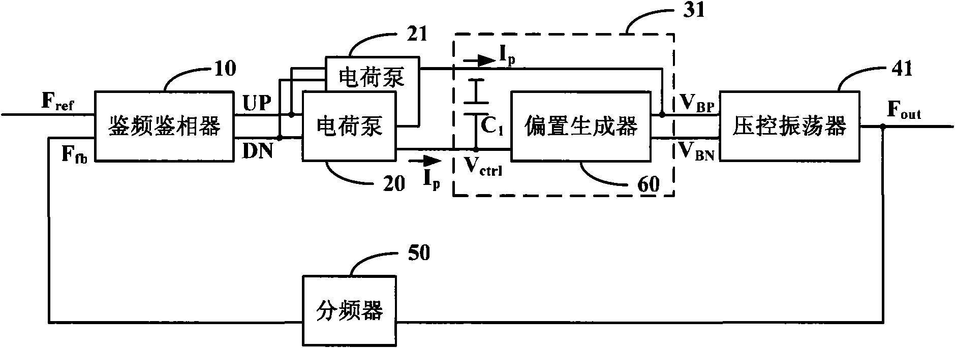
[0051] The specific implementation of the present invention will be described in detail below in conjunction with the accompanying drawings and embodiments. Figure 5 It is a schematic diagram of the basic structure of a self-biased phase-locked loop according to an embodiment of the present invention. The self-biased phase-locked loop includes: a frequency and ph...


PUM


Abstract

The invention relates to a self-biased phase-locked loop which comprises a phase frequency detector, a charge pump, a loop filter, a voltage controlled oscillator, a frequency demultiplier and a biased current converter, wherein charging or discharging current output by the charge pump is equal to a first control current; a resistor of the loop filter is controlled by a first control voltage and a second control voltage, the second control voltage is adjusted according to the first control voltage and a second control current, and the loop filter increases or reduces the first control voltage according to the charging or discharging current output by the charge pump; the voltage controlled oscillator generates oscillating voltage and biased current according to the first control voltage, and accelerates or slowers oscillating frequency according to the increase or the reduction of the oscillating voltage; and the biased current converter converts the biased current to a first control current and the second control current, wherein the first control current is equal to the ratio of the biased current and a constant; and the second control current is equal to the ratio of the biased current and the frequency demultiplication number of the frequency demultiplier. The self-biased phase-locked loop has the characteristics of simple current and low dithering.

Description

technical field [0001] The invention relates to phase-locked loop technology, in particular to a self-biased phase-locked loop. Background technique [0002] A phase-locked loop (PLL, Phase Locked Loop) is widely used in a system-on-chip (SOC, Systemon Chip) to form a frequency synthesizer, a clock generator, and the like. figure 1 It is a basic phase-locked loop structure, and a Phase Frequency Detector (PFD, Phase Frequency Detector) 10 detects the input signal F ref and the feedback signal F fb Frequency difference and phase difference, produce pulse control signal UP, DN and send into charge pump (CP, chargepump) 20; In charge pump 20, pulse control signal UP, DN are converted into current I p To the capacitor C of the loop filter (LP, Loop Filter) 30 p charging and discharging, the loop filter 30 generates a control voltage V ctrl into a voltage-controlled oscillator (VCO, Voltage Control Oscillator) 40; the voltage-controlled oscillator 40 controls the voltage V c...

Claims


Application Information

Patent Timeline
Patent Type & Authority Applications(China)
IPC IPC(8): H03L7/18H03L7/093H03L7/099H03K19/0185
CPCH03L7/0898H03L7/0995H03L7/093H03L7/0895
Inventor 符志岗
Owner SEMICON MFG INT (SHANGHAI) CORP
Why Eureka
Try Eureka