
Interlacing removal method, interlacing removal device and video processing system for video data

A video data and de-interlacing technology, which is applied in the field of video processing, can solve the problems of unclear images, increase the pixel value error of interpolation points, and low accuracy, and achieve the effects of improving clarity, reducing pixel errors, and improving accuracy

Inactive Publication Date: 2009-11-25
HUAWEI TECH CO LTD
View PDF0 Cites 8 Cited by
  • Summary
  • Abstract
  • Description
  • Claims
  • Application Information

AI Technical Summary

Problems solved by technology

[0005] However, the existing technology only detects the pixel changes of the front and rear top fields, but cannot detect the pixel changes of the bottom field between the front and rear top fields, resulting in missed detection, resulting in incorrect pixel values ​​of interpolation points after interpolation It reflects the change of the bottom field that is missed, and ultimately affects the clarity of the image, and predicts whether the pixels of the interpolation line in the top field move by detecting whether the detection point in the top field moves. This judgment method is not accurate. High, it is easy to cause misjudgment, and ultimately affect the unclear image. At the same time, in the process of moving pixel points, only the pixel value in the vertical direction is used, which will increase the pixel value error of the interpolation point. resulting in unclear images

Method used


Image

  • Interlacing removal method, interlacing removal device and video processing system for video data
  • Interlacing removal method, interlacing removal device and video processing system for video data
  • Interlacing removal method, interlacing removal device and video processing system for video data

Examples


Embodiment Construction

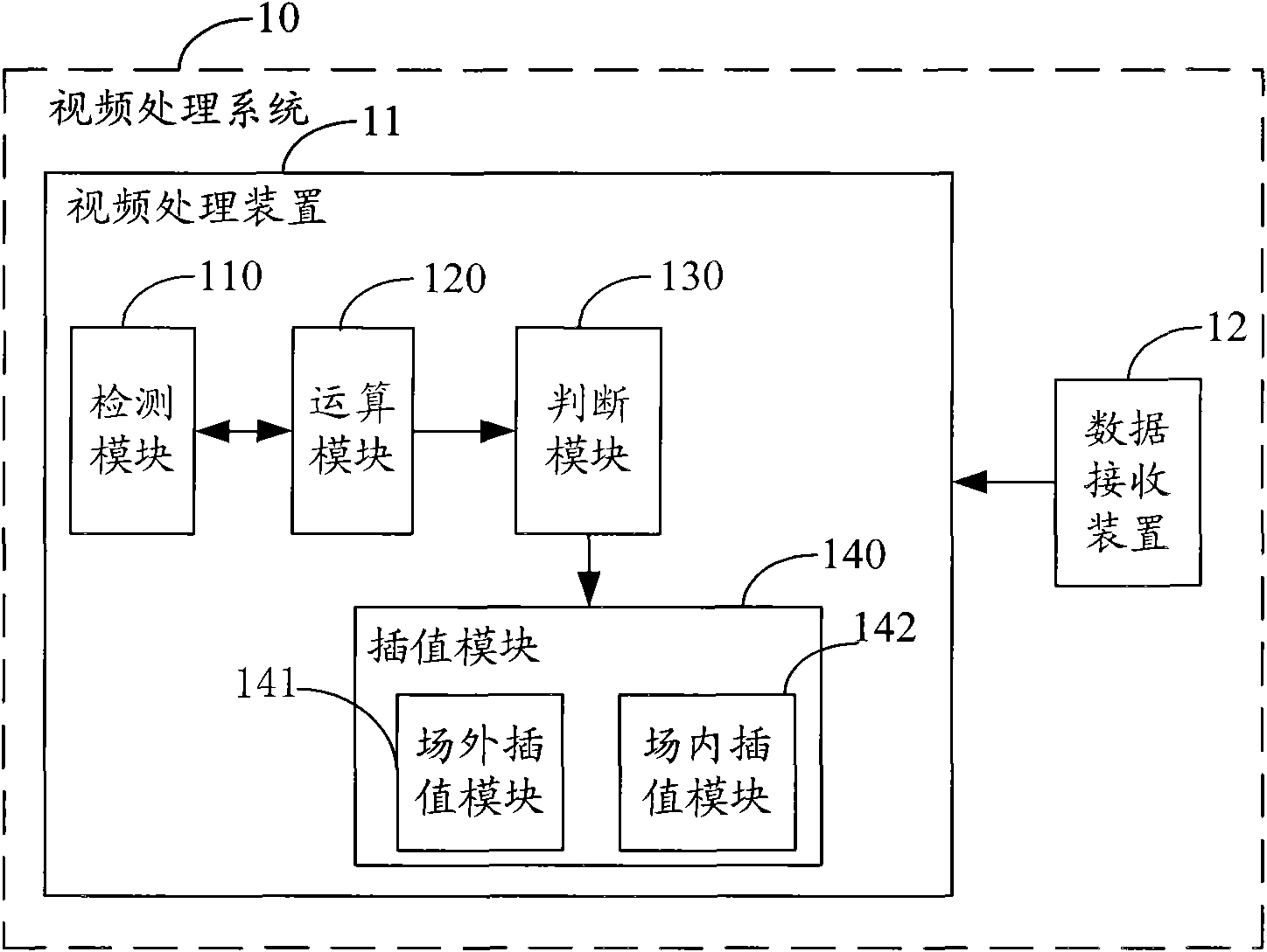
[0039] figure 1 Shown is a structural diagram of the video processing system 10 of the present invention. In this embodiment, the video processing system 10 includes a data receiving device 12 and a de-interlacing device 11, the data receiving device 11 is used for receiving video data, and the de-interlacing device 11 is used for de-interlacing the received video data.

[0040]In this embodiment, the video processing device 11 includes a detection module 110 , an operation module 120 , a judgment module 130 , and an interpolation module 140 . The interpolation module 140 includes an intra-field interpolation module 141 and an inter-field interpolation module 142 . The detection module 110 is used to detect the motion state of the pixels of the top field of the current frame relative to the pixels at the same spatial position of the top field of the adjacent frame in the video data, and detect the motion state of the pixels of the bottom field of the current frame relative to...


PUM


Abstract

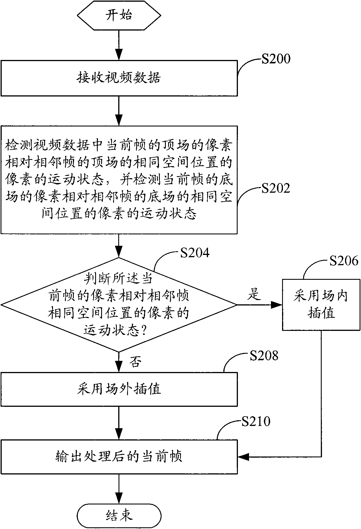
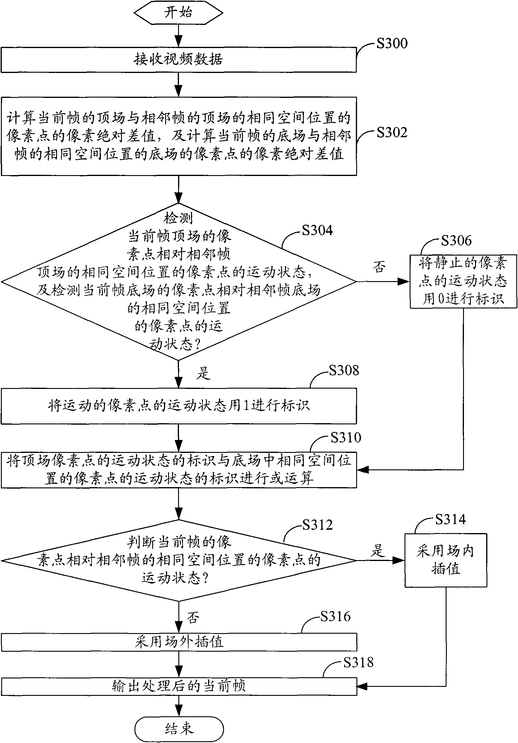
The embodiment of the invention discloses an interlacing removal method for video data, comprising the following steps: detecting the motion state of the pixel of the top field of a current frame in video data relative to the pixel of the same spatial location of the top field of an adjacent frame, and detecting the motion state of the pixel of the bottom field of the current frame relative to the pixel of the same spatial location of the bottom field of the adjacent frame; judging the motion state of the pixel of the current frame relative to the pixel of the same spatial location of the adjacent frame by judging whether at least one pixel of the pixels of the same spatial locations of the top field and the bottom field of the current frame is in motion state or not; and carrying out interpolation according to the motion state. The embodiment of the invention also provides an interlacing removal device and a video processing system for video data. By the embodiment of the invention, the pixel of the current frame is free from detection omission, the accuracy of judging the motion state of the pixel of the current frame is enhanced, the pixel error of a point to be interpolated is reduced, and the definition of an image is enhanced.

Description

technical field [0001] Embodiments of the present invention relate to the field of video processing, and in particular, to a method for deinterlacing video data, a deinterlacing device, and a video processing system. Background technique [0002] With the continuous development of digital technology and the continuous entry of high-resolution display devices into the video consumption market, consumers have higher and higher requirements for multimedia. As interlaced scanning technology is commonly used in the video field, consumers find that on high-resolution display devices, interlaced scanning technology will have the disadvantages of line crawling, edge feathering and interlacing, resulting in interlaced scanning technology that cannot meet consumers' high multimedia requirements. Require. [0003] In order to eliminate the above defects, operators have introduced a technology for converting interlaced video into progressive video, that is, De-interlacing, also known a...

Claims


Application Information

Patent Timeline
Patent Type & Authority Applications(China)
IPC IPC(8): H04N5/14H04N7/01H04N5/44
CPCH04N7/012H04N5/144
Inventor 谢清鹏高新波周芳邓勤耕张晓森熊联欢
Owner HUAWEI TECH CO LTD
Learn More