Supercharge Your Innovation With Domain-Expert AI Agents!

Multiple phase pulse generator

A pulse generator and generator technology, applied in pulse processing, pulse technology, instruments, etc., can solve the problems of increasing the circuit complexity of control registers, increasing the number of display connections, not reversing the scanning direction, etc., to reduce the number of connections , reduced area, simple circuit

Inactive Publication Date: 2012-07-18
SHARP KK
View PDF8 Cites 0 Cited by
  • Summary
  • Abstract
  • Description
  • Claims
  • Application Information

AI Technical Summary

Problems solved by technology

[0010] However, this type of shift register has two disadvantages when it is required to generate pulses for the scan driver: first, the pulses have coincident edges (i.e. when Q i Q when falling i+1 rising), and second, there is no easy way to reverse its scan direction
However, this register requires at least three clock signals, and since its outputs overlap, additional logic and / or signals are required to generate non-overlapping output pulses
This additional clock increases the complexity of the circuitry controlling the registers and, in the case of registers formed on the display substrate, increases the number of connections to the display

Method used


Image

  • Multiple phase pulse generator
  • Multiple phase pulse generator
  • Multiple phase pulse generator

Examples


Embodiment Construction

[0046] Figure 8 and 9 The first embodiment is shown in . Figure 8 Connections between adjacent stages - registers 28, 30 and 32 - are shown. Each stage has two inputs IN1 and IN2, a clock input CK, a reset input RST, a "lock" output LOCK and the main output OUT. For stage n, IN1 and IN2 are connected to the lock output LOCK of the adjacent stage n+1 and LOCK n-1 , CK is connected to the register clock CK, RST is connected to the global reset signal RST, and LOCK is connected to the input IN2 of two adjacent stages n+1 and IN1 n -1 , OUT is connected to the nth output OUT of the register n .

[0047] In the case of the leftmost stage 28 and the rightmost stage 32, one of the inputs is connected to receive the start pulse. IN2 of stage 28 is connected to receive the left start pulse START L ;IN1 of stage 32 is connected to receive the right start pulse START R .

[0048] Figure 9 show Figure 8 The composition of the first level. The first storage element is im...


PUM


Abstract

A multiple phase pulse generator comprises n stages, where each stage comprises a first sub-stage (34, 38, 39, 40) and a second sub-stage (36, 42, 44). The first sub-stage has a first memory element (34) and the second sub-stage has a second memory element (36). The first memory element (34) of each stage is arranged to be set by the preceding stage. The first sub-stage (34, 38, 39 40) is arrangedto supply a stage output pulse (OUT) while the first memory element (34) is set. The second memory element (36) is arranged to be set by the stage output pulse (OUT). The second sub-stage (36, 42, 44) is arranged to hold the first memory element (34) reset after the stage output pulse (OUT) while the second memory element (36) is set.

Description

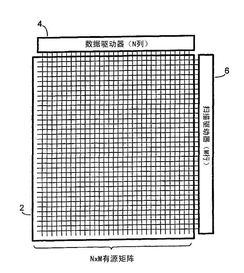
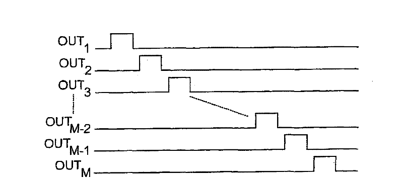
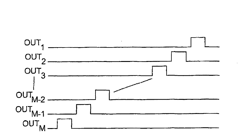
technical field [0001] The invention relates to a multiphase pulse generator. This generator can be used in devices such as displays. Background technique [0002] figure 1 A typical active matrix display is shown. The display consists of a matrix 2 of picture elements (pixels) arranged in M ​​rows and N columns. Each row and column is connected to one electrode, wherein the column electrodes are connected to the N outputs of the data driver 4 , and the row electrodes are connected to the M outputs of the scan driver 6 . [0003] Pixels are addressed one row at a time. The scan driver includes generating figure 2 A series of clock pulses is shown for the M-phase clock generator. Each clock phase OUT i Controls the activation of row i. Usually the pulses are non-overlapping, so no two pulses are high at the same time. [0004] All pixels of a row can be addressed simultaneously, or they can be addressed in B blocks of b pixels, where bB=N. In the latter case, the d...

Claims


Application Information

Patent Timeline
Patent Type & Authority Patents(China)
IPC IPC(8): H03K5/00
CPCG11C19/28G09G3/3674G09G2310/0283G09G3/3677G09G3/3688H03K5/15093
Inventor P·泽贝迪
Owner SHARP KK
Features
  • R&D
  • Intellectual Property
  • Life Sciences
  • Materials
  • Tech Scout
  • Unparalleled Data Quality
  • Higher Quality Content
  • 60% Fewer Hallucinations
Learn More