Stirring shaft of banburymixer

A mixer and agitating shaft technology, applied in mixers, mixers with rotary stirring devices, dissolving and other directions, can solve the problems of low production efficiency, long time required, long mixing time, etc., and achieve high uniformity, The effect of facilitating heat dissipation and shortening the mixing cycle time

Inactive Publication Date: 2009-12-02
南京凯驰机械有限公司
View PDF0 Cites 7 Cited by
  • Summary
  • Abstract
  • Description
  • Claims
  • Application Information

AI Technical Summary

Problems solved by technology

When the first and second rotors rotate relative to each other, in the radial direction, the wave plates 13, 14 of the first rotor do not overlap with the wave plates 23, 44 on the second rotor 2, that is to say, the first rotor 1, The second rotor 2 actually rotates independently to knead and stir the materials (a mixture of polymer materials and additives), so it takes a long time to mix the mixture evenly, the kneading time is long and the production efficiency is low

Method used


Image

  • Stirring shaft of banburymixer
  • Stirring shaft of banburymixer
  • Stirring shaft of banburymixer

Examples


Embodiment Construction

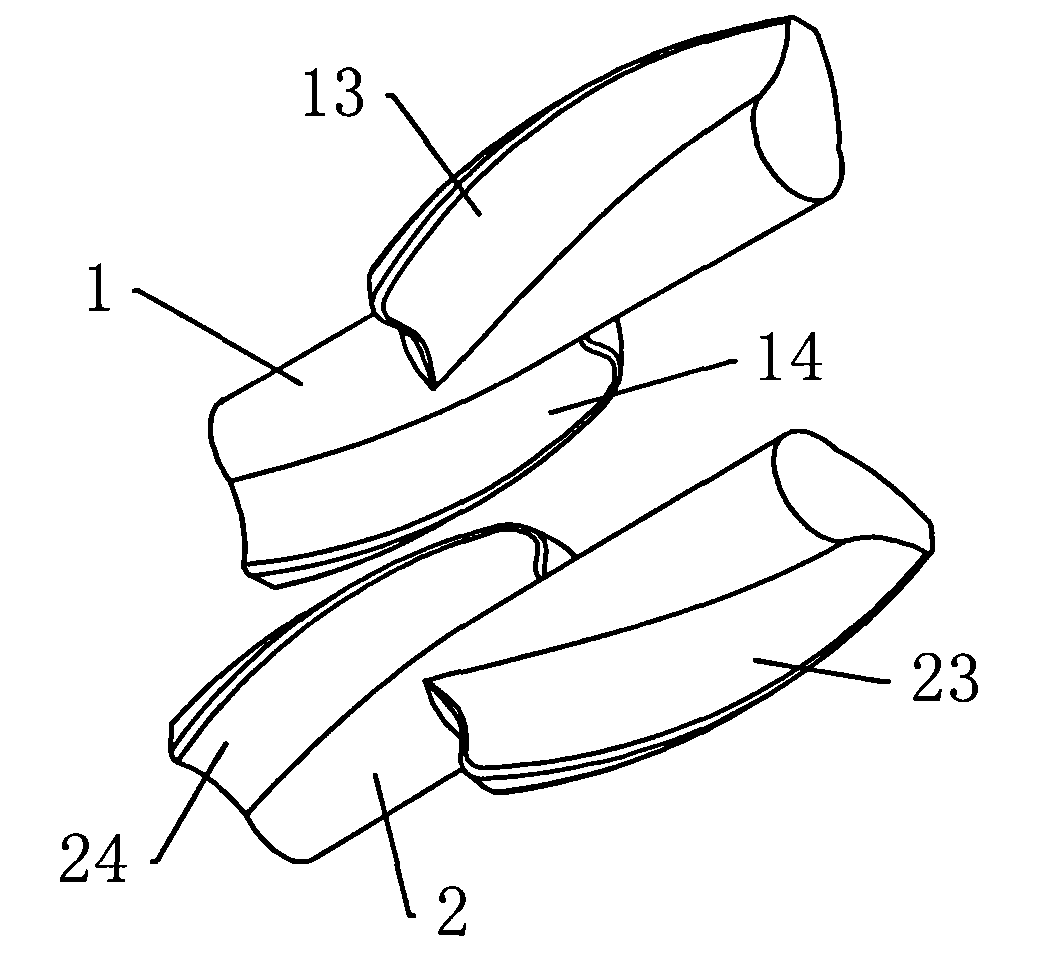
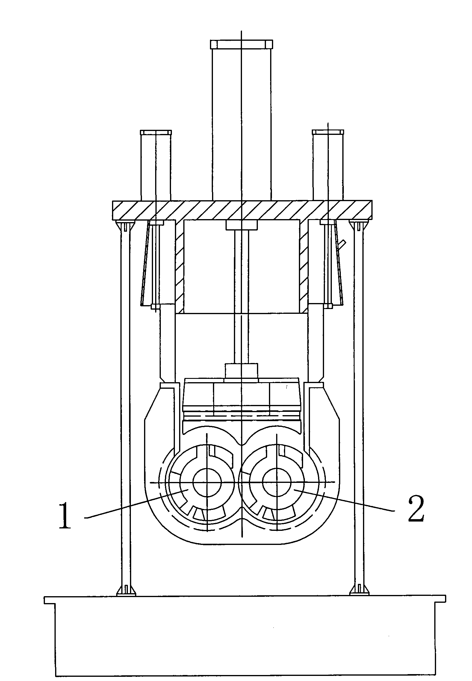
[0016] As shown in the figure, the mixing shaft of the internal mixer includes two parallel first rotors 1 and second rotors 2 that rotate relatively under the drive of the power mechanism. There are spiral ribs 13 on the cylindrical surface of the first rotor. A boss 14 is respectively set on the cylindrical surface at both ends of the first rotor; a helical rib 23 is arranged on the cylindrical surface of the first rotor, and a boss 24 is respectively arranged on the cylindrical surface at the two ends of the second rotor. When the first rotor 1 and the second rotor 2 rotate relative to each other, the protrusion 14 and the helical rib 13 on the first rotor extend into the gap between the helical rib 23 and the protrusion 24 on the second rotor successively; The protrusion 24 and the helical rib 23 on the second rotor successively extend into the gap between the helical rib 13 and the protrusion 14 on the first rotor. The surfaces of the first rotor and the second rotor are ...


PUM


Abstract

The invention aims to provide a stirring shaft of an energy-saving banburymixer, which can make the uniformity of mixing molecules higher, shorten mixing period and improve production efficiency. The stirring shaft is provided with two rotors which have a meshing type prism structure in synchronous opposite rotation; and the aim of mixing is achieved by linear speed difference. The stirring shaft comprises two parallel rotors which are driven by a power unit to rotate relatively; the cylindrical surfaces of the two rotors are all provided with spiral ribs, and the cylindrical surfaces of the two rotors at two ends are all provided with lug bosses; and when the two rotors rotate relatively, the lug bosses and the spiral ribs on one rotor extend into clearances between the spiral ribs and the lug bosses on the other rotor in turn.

Description

technical field [0001] The invention relates to a stirring shaft of a banbury mixer. Background technique [0002] The stirring shaft of the existing internal mixer is shown in the figure. It includes two parallel first rotors 1 and second rotors 2 that rotate relative to each other. The corrugated sheets 13, 14 are respectively provided with corrugated sheets 23, 44 in opposite helical directions on the second rotor 2 along the axial direction. When the first and second rotors rotate relative to each other, in the radial direction, the wave plates 13, 14 of the first rotor do not overlap with the wave plates 23, 44 on the second rotor 2, that is to say, the first rotor 1, The second rotor 2 actually rotates independently to knead and stir the materials (the mixture of polymer materials and additives), so it takes a long time to mix the mixture evenly, the kneading time is long, and the production efficiency is low. This stirring shaft is also called a tangential stirring ...

Claims


Application Information

Patent Timeline
Patent Type & Authority Applications(China)
IPC IPC(8): B01F7/08B29B7/20
CPCB29B7/183B29B7/186
Inventor 陈建伟
Owner 南京凯驰机械有限公司
Why Eureka
Try Eureka