Axial bearing seals for exhaust gas turbochargers

An exhaust gas turbine and axial bearing technology, which is used in the lubrication of gas turbine devices, turbine/propulsion devices, shafts and bearings, etc., can solve problems such as follow-up that cannot overcome pressure gradients

Inactive Publication Date: 2011-11-30
MAN ENERGY SOLUTIONS SA
View PDF2 Cites 0 Cited by
  • Summary
  • Abstract
  • Description
  • Claims
  • Application Information

AI Technical Summary

Problems solved by technology

[0013] However, in this type of turbocharger it is also possible for the centrifugal force in the rotating liquid ring of the axial bearing to generate a pressure gradient which is greater than the pressure gradient of the oil in the oil inlet of the stationary bearing body. Delivery pressure, so the oil cannot overcome this pressure gradient and follow

Method used


Image

  • Axial bearing seals for exhaust gas turbochargers
  • Axial bearing seals for exhaust gas turbochargers

Examples


Embodiment Construction

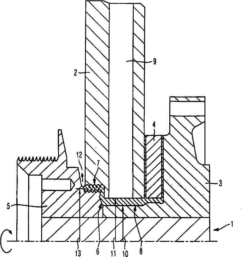
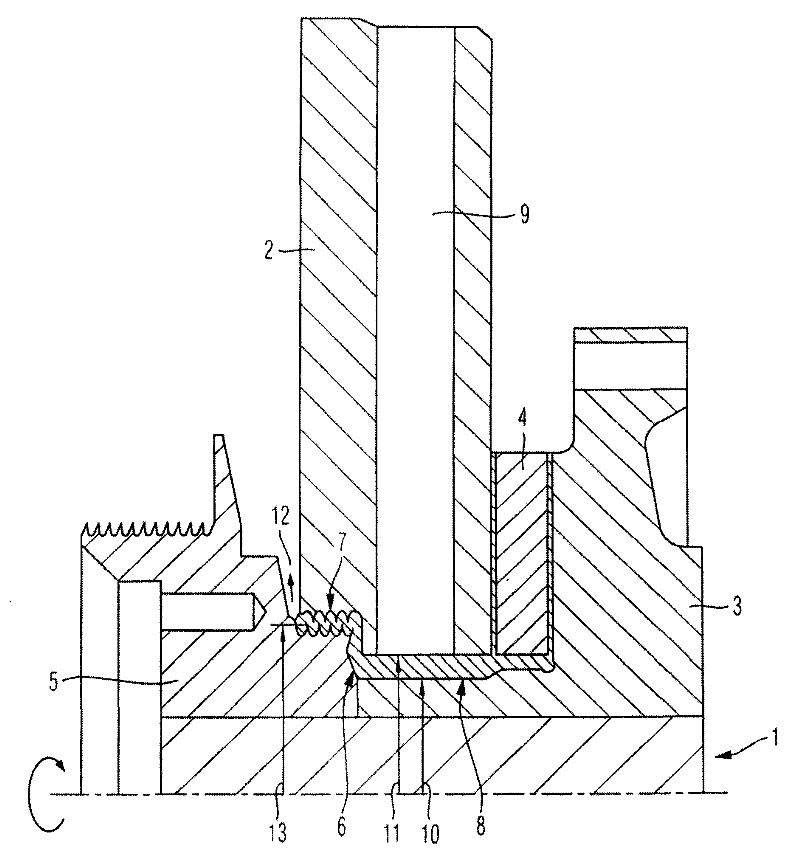
[0022] The axial bearing seal according to the invention comprises a bearing body 2 fixed to the housing of the exhaust gas turbocharger and fixed relative to the rotor shaft 1, a further bearing body in the form of a bearing ring rotating with the rotor shaft 1 3 and the sealing ring 5 that is connected to the fixed bearing body 2 on the side of the compressor housing along the axial direction of the rotor shaft 1 toward the compressor housing. A floating disc 4 is contained between the stationary bearing body 2 and the rotating bearing ring 3 .

[0023] A sealing gap 6 is formed between the sealing ring 5 and the stationary bearing body 2 , wherein the sealing ring 5 has an additional labyrinth seal 7 in the exemplary embodiment shown. Of course, other sealing arrangements are also conceivable here.

[0024] Between the surface of the rotor shaft 1 and the axial bore of the stationary bearing body 2 there is an oil chamber 8 in the form of a rotating liquid ring, through wh...


PUM


Abstract

The seal has a stationary bearing housing (2) cooperating with a bearing collar (3) rotating with a rotor shaft (1). An oil chamber (8) is provided between a surface of the shaft and an axial drill of the bearing housing. The seal ring has a seal (7) i.e. labyrinth seal, operating in an axial direction. A sealing gap (6) is formed between a rotary seal ring (5) and the housing with respect to the shaft such that the oil pressure existing in the gap during operation of the exhaust-gas turbocharger is larger than air pressure in an axial bearing.

Description

technical field [0001] The invention relates to an axial bearing seal according to the preamble of claim 1 for an exhaust gas turbocharger having a rotor shaft which is at one end in a turbine housing The turbine wheel is mounted guided in the housing bore, and the compressor wheel is mounted guided at the other end in the housing bore in the compressor housing. Background technique [0002] The rotor shaft is usually supported on radial and axial bearings, including a suitable lubrication system, which are arranged inside an intermediate bearing housing which is connected between the turbine housing and the compressor housing. [0003] Here, at least in the region of the compressor wheel or the compressor housing, an axial bearing for the rotor shaft is provided, which has a seal which is connected to, for example, a floating disk or a fixed section or a tilting section The oil seal components interact. [0004] It is known here that oil is delivered to the bearing housin...

Claims


Application Information

Patent Timeline
Patent Type & Authority Patents(China)
IPC IPC(8): F02B39/14F02C6/12F02C7/06
CPCF01D25/168F05D2220/40F05B2220/40F01D25/186F02C6/12F16C33/66F16C33/72F16J15/447
Inventor F·沃德克D·武茨M·斯彭格勒T·西沃特
Owner MAN ENERGY SOLUTIONS SA
Why Eureka
Try Eureka