Automatic film coating device

一种镀膜装置、驱动装置的技术,应用在喷射装置、溅射镀覆、真空蒸发镀覆等方向,能够解决增加镀膜周期、双面镀膜层膜特征不一致、无法保持真空室参数一致性等问题,达到减少镀膜的时间、减少加热和抽真空次数的效果

Inactive Publication Date: 2009-12-09
HONG FU JIN PRECISION IND (SHENZHEN) CO LTD +1
View PDF0 Cites 12 Cited by
  • Summary
  • Abstract
  • Description
  • Claims
  • Application Information

AI Technical Summary

Problems solved by technology

[0003] However, in the existing vacuum coating equipment, only one side of the substrate can be coated at a time. If you want to coat it on both sides, you need to open the coating machine to destroy its vacuum state; The temperature in the chamber is extremely high, so it needs to be cooled down and taken out, then turned over and put back into the vacuum chamber. At this time, it needs to be reheated and evacuated, which will increase the coating cycle and the number of times of vacuuming, and cannot maintain the vacuum chamber. The parameter consistency of the degree of vacuum will make the film characteristics of the double-sided coating layer of the substrate inconsistent

Method used


Image

  • Automatic film coating device
  • Automatic film coating device

Examples


Embodiment Construction

[0009] The present invention will be further described in detail below in conjunction with the accompanying drawings.

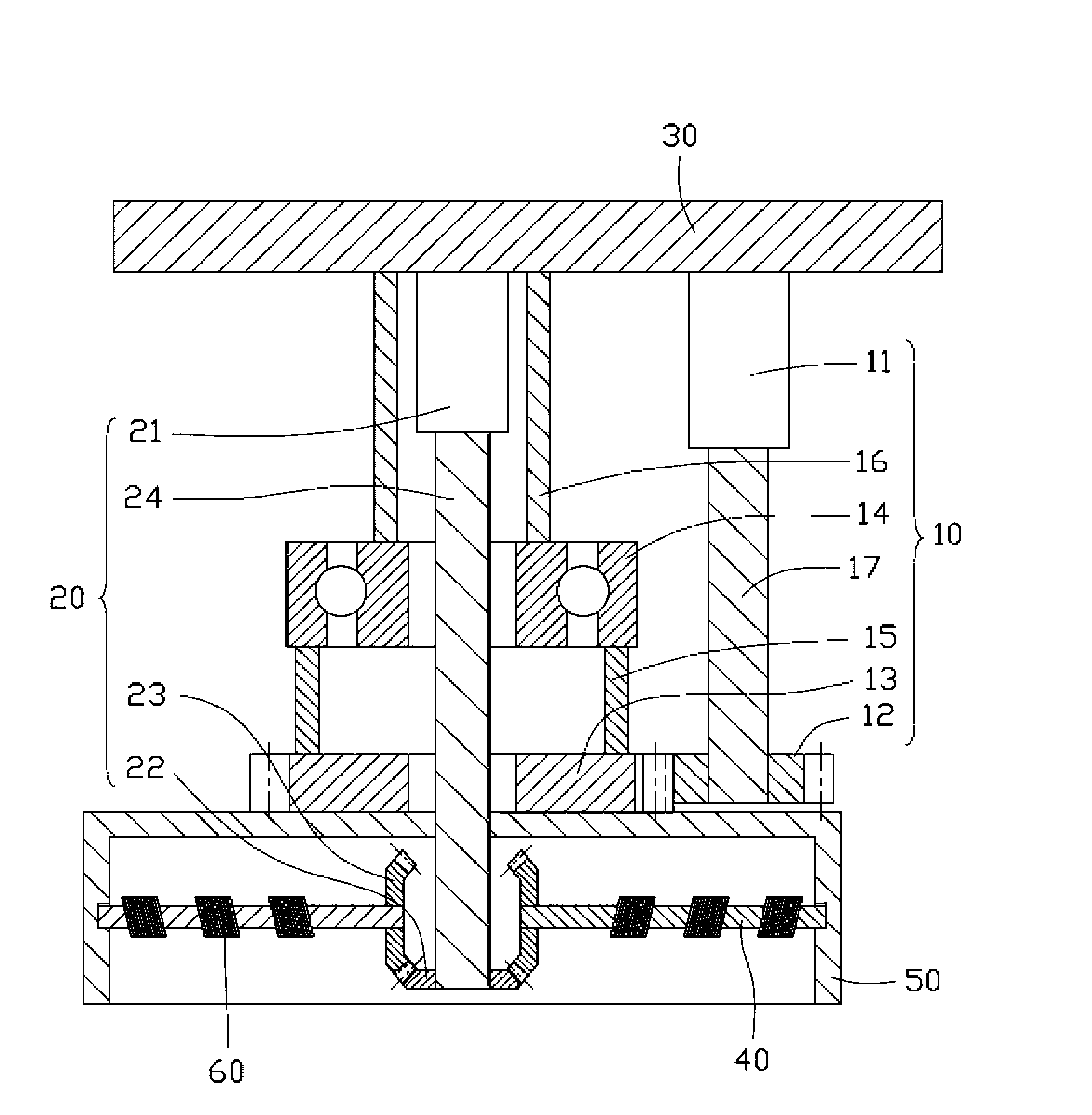
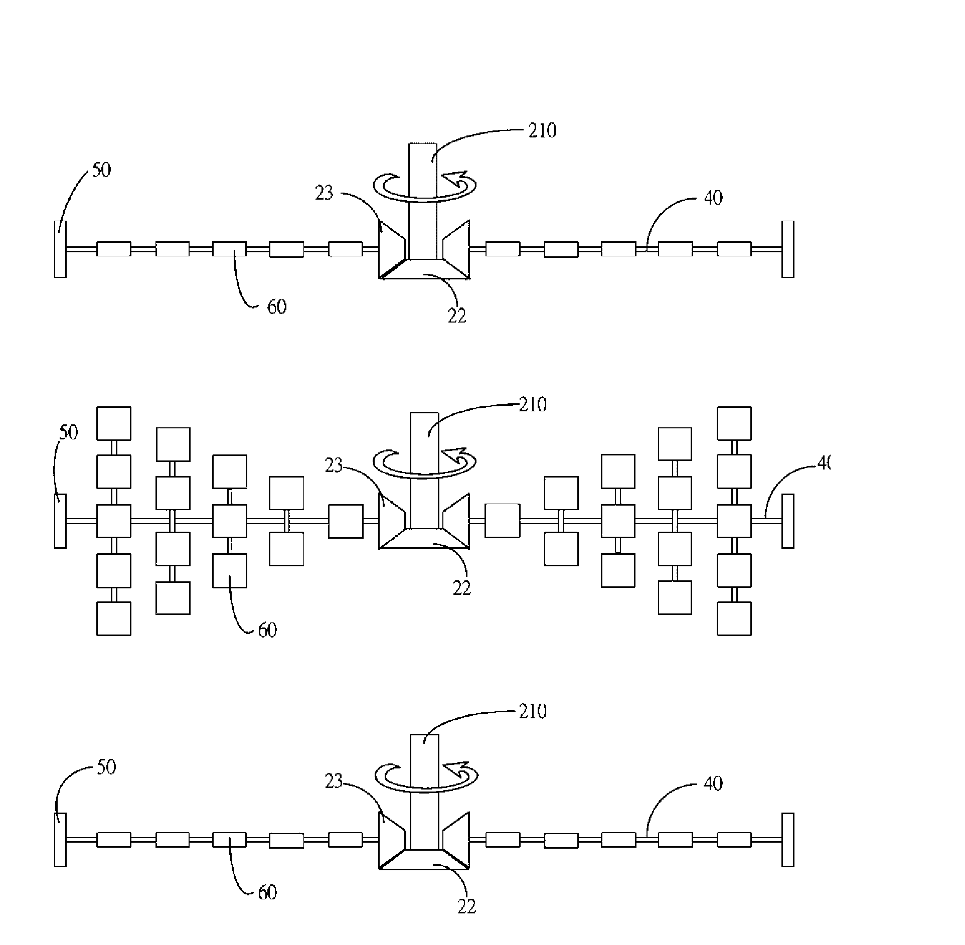
[0010] see figure 1 and figure 2 , the automatic coating device 100 provided by the embodiment of the present invention includes a rotating device 10 , a turning device 20 , a machine body 30 , a substrate 40 and a supporting frame 50 .

[0011] The rotating device 10 includes: a first driving device 11 , a rotating driving gear 12 , a rotating driven gear 13 , a bearing 14 , a connecting rod 15 , a fixed rod 16 and a first transmission shaft 17 . The first driving device 11 is fixed on the top of the body 30; the rotating drive gear 12 is connected to the other end of the first transmission shaft 17 fixed on the first driving device 11, and the first transmission shaft 17 drives the rotating driving gear 12 rotates; the rotating driven gear 13 meshes with the rotating driving gear 12, and the rotating driving gear 12 drives the rotating driven gear 13 to ...


PUM


Abstract

The invention discloses an automatic film coating device comprising a machine body, a support frame, a substrate, a rotation device and a turnover device; wherein, the rotation device comprises a first driving device and a first transmission shaft connected with the first driving device; the turnover device comprises a second driving device and a second transmission shaft connected with the second driving device; the first driving device and the second driving device are adjacently fixed on the top of the machine body, and the first transmission shaft and the second transmission shaft are mutually parallel; one end of the support frame is rotatablely connected to the machine body, and the substrate is rotatablely connected to the support frame; the first driving device drives the first transmission shaft so as to drive the support frame to rotate horizontally, and the second driving device drives the second transmission shaft so as to drive the substrate to rotate vertically. The automatic film coating device of the invention can ensure that when one surface of a base wafer to be coated on the substrate finishes coating films, the other surface can perform film coating after automatic turnover without lowering temperature and breaking vacuum.

Description

technical field [0001] The invention relates to a coating device, in particular to an automatic coating device. Background technique [0002] At present, the physical vapor deposition method (Physics Vapor Deposition, referred to as PVD) is the main method of optical thin film production. This method converts the film material from solid state to gaseous or ionic state material. The evaporation source travels through the space and reaches the glass surface, and the film material reaches the glass. Thin films are gradually formed after deposition on the surface (see "Current Status and Development of Vacuum Coating Technology", Wang Yinchuan, "Modern Instruments", No. 6, 2000, pages 1-4). Usually, in order to make the thin film have high purity, the coating process must be completed in a high vacuum environment. Vacuum coating is extended from this. The general method is to clean the substrate with an ultrasonic cleaning machine. After cleaning, the substrate is placed on th...

Claims


Application Information

Patent Timeline
Patent Type & Authority Applications(China)
IPC IPC(8): C23C14/26
CPCB05B13/0228C23C14/505
Inventor 吴佳颖
Owner HONG FU JIN PRECISION IND (SHENZHEN) CO LTD
Why Eureka
Try Eureka