Drive circuit of light emitting diode

A technology of light-emitting diodes and driving circuits, which is applied to semiconductor devices of light-emitting elements, circuit layout, electric lamp circuit layout, etc., can solve problems such as inability to accurately adjust brightness and different target brightness.

A technology of light-emitting diodes and driving circuits, which is applied to semiconductor devices of light-emitting elements, circuit layout, electric lamp circuit layout, etc., can solve problems such as inability to accurately adjust brightness and different target brightness.

CN101600279AInactive Publication Date: 2009-12-09普照光电科技股份有限公司

Image

  • Drive circuit of light emitting diode
  • Drive circuit of light emitting diode
  • Drive circuit of light emitting diode

Examples


Embodiment Construction

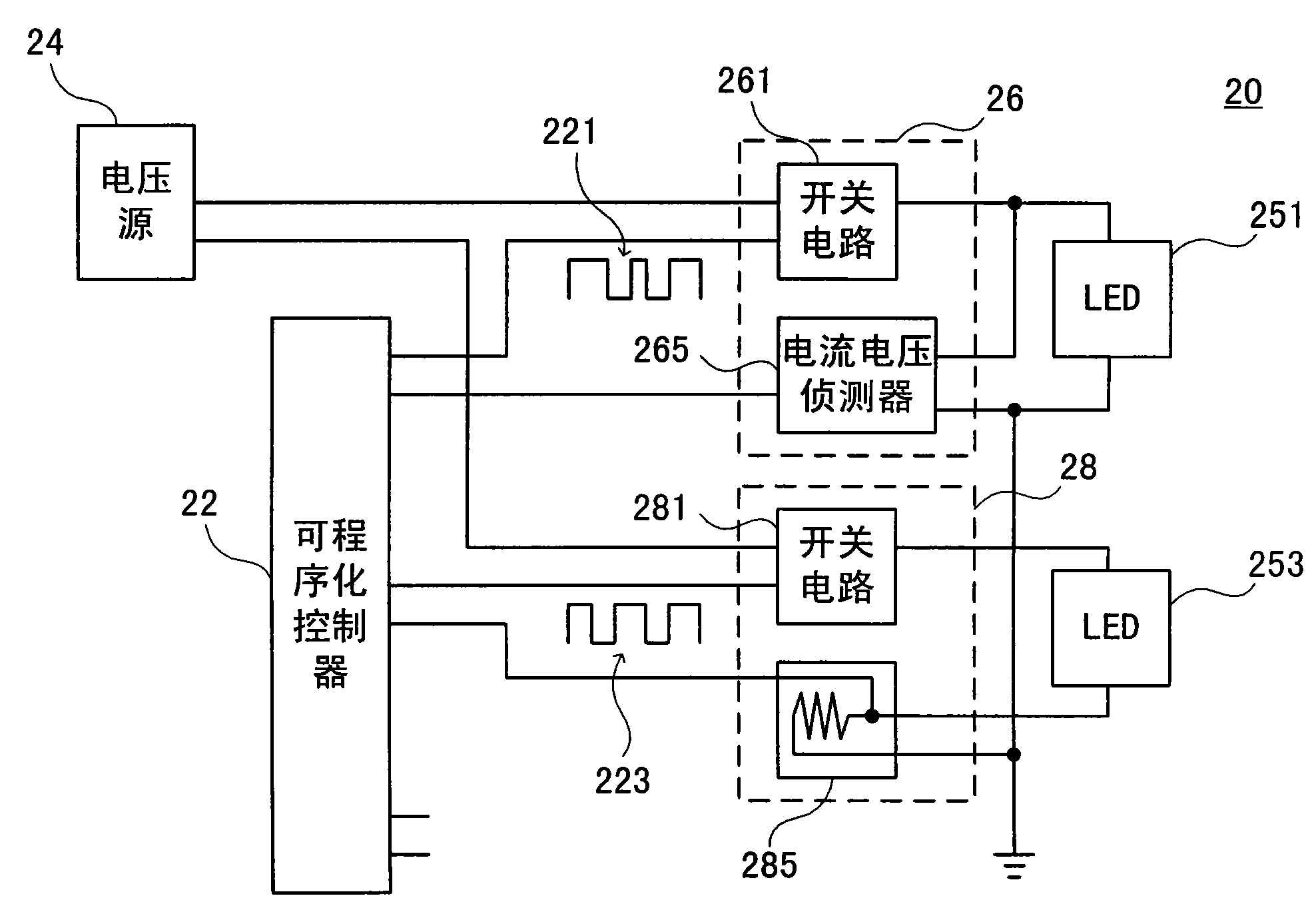
[0054] see figure 2 , is a circuit block diagram of a preferred embodiment of the present invention. As shown in the figure, the driving circuit 20 of the light emitting diode (LED) of the present invention mainly includes a voltage source 24, at least one driving module (26, 28), at least one LED (251, 253) and a programmable controller twenty two. In this embodiment, two sets of drive modules 26 and 28 are used as an example for illustration.

[0055] Wherein, each driving module 26 , 28 includes a switch circuit 261 , 281 and a current and voltage detector 265 , 285 respectively, and each driving module 26 , 28 is connected to an LED 251 , 253 respectively. Wherein, the LED 251 and 253 can be one LED, or multiple LEDs connected in series or in parallel.

[0056] The switch circuits 261, 281 of the driving modules 26, 28 are respectively connected to the voltage source 24, and the LEDs 251, 253 and the corresponding current and voltage detectors 265, 285 are respectively...


PUM


Abstract

The invention discloses a drive circuit of a light emitting diode, in particular to a drive circuit of the light emitting diode, which can be accurately controlled and accurately dim light. The drive circuit mainly comprises a voltage source for proving working voltage, at least one drive module, at least one light emitting diode and a programmable controller, wherein each drive module comprises a switch circuit and a current and voltage detector respectively. The drive circuit utilizes the programmable controller to connect the switch circuit and the current and voltage detector of each drive module, can adjust a switch state of the switch circuit according to a current signal or a voltage signal of the current and voltage detector and respectively and accurately control current passing through each light emitting diode or voltage applied to each light emitting diode.

Description

technical field [0001] The invention relates to a driving circuit of a light emitting diode, in particular to a driving circuit of a light emitting diode capable of precise control and precise dimming. Background technique [0002] see figure 1 , is a block diagram of an existing light-emitting diode (LED) driving circuit. As shown in the figure, it mainly uses a voltage source 12 to provide a working voltage to an LED 14 , the LED 14 is connected to a switch circuit 165 , and a current detector 18 is connected in series behind the switch circuit 165 . [0003] Wherein, the current detector 18 is usually a resistor, and detects the current by using the voltage drop generated by the current flowing through the resistor. Connect the current detector 18 to a comparator circuit 161, compare the voltage obtained by the current detector 18 with the triangular wave 169 generated by a waveform generator 163, when the voltage of the triangular wave 169 is greater than the voltage o...

Claims


Application Information

Patent Timeline
09 Dec 2009
Publication
CN101600279A
IPC
H05B37/00; H05B37/02; F21V23/00; F21Y101/02; F21Y115/10
Inventors
陈元杰; 石晏竹