Clamp with one surface and two pins and manufacture method thereof

A manufacturing method and pin positioning technology, applied in positioning devices, manufacturing tools, clamping and other directions, can solve the problems of long replacement cycle, inflexible replacement, and high replacement cost, and achieve short replacement time and flexible replacement. , the effect of small replacement investment

Active Publication Date: 2013-04-17
GUANGXI YUCHAI MASCH CO LTD
View PDF0 Cites 1 Cited by
  • Summary
  • Abstract
  • Description
  • Claims
  • Application Information

AI Technical Summary

Problems solved by technology

The traditional fixture has the advantages of simple structure, good reliability, and low manufacturing cost, but at the same time has the disadvantages of long cycle time, high cost, and inflexibility.

Method used


Image

  • Clamp with one surface and two pins and manufacture method thereof
  • Clamp with one surface and two pins and manufacture method thereof
  • Clamp with one surface and two pins and manufacture method thereof

Examples


Embodiment Construction

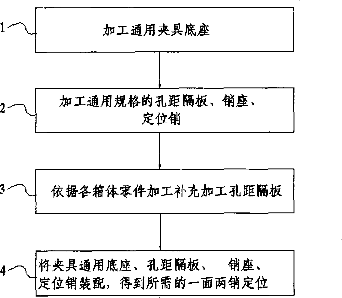
[0041] figure 1 It is a flow chart of the manufacturing method of one side two-pin positioning fixture of the present invention, comprising steps:

[0042] Step 1. Process the universal fixture base;

[0043] Step 2. Process hole spacing partitions, pin hole seats, and positioning pins of general specifications;

[0044] Step 3. According to the size of the hole distance of each box body part, the hole distance partition is shortened to the corresponding length;

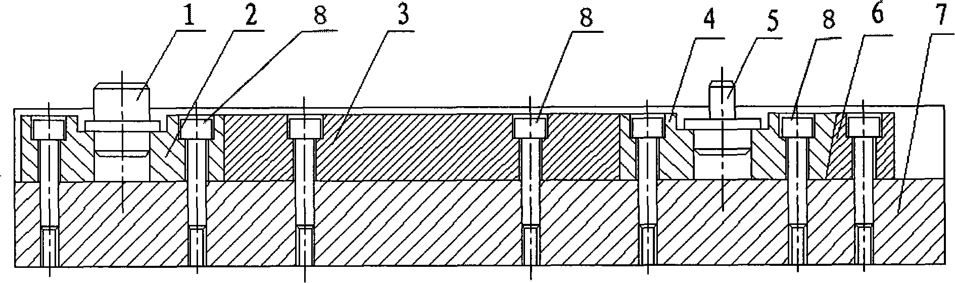
[0045] Step 4. Assemble the common base of the fixture, the hole distance partition, the pin hole seat, and the positioning pin to obtain the required positioning of two pins on one side.

[0046] Among them, step 1 is specifically:

[0047] Step 11, casting the universal fixture base;

[0048] Step 12. Process the base of the universal fixture, and process the mounting grooves for the partition and the mounting screw holes.

[0049] Among them, step 2 is specifically:

[0050] Step 21, processing the hole-dis...


PUM


Abstract

The invention discloses a clamp with one surface and two pins and a manufacture method thereof. The method comprises the following steps: processing a clamp base; processing a pitch clapboard, a first pin hole seat, a second pin hole seat and a locating pin; additionally processing grid spacers according to the sizes of parts of each box body; and assembling the clamp base, the pitch clapboard, the pin hole seats and the locating pin to obtain the clamp with one surface and two pins. The method rapidly obtains a needed locating datum by the additional processing of the pitch clapboard. Compared with the traditional method in which one base is manufactured by using variety of box-type parts, the invention has the characteristics of little investment, simple and effective technology, flexible type change, and the like, on the condition of meeting the requirement of the product, thereby being suitable for production of box-type parts of various specifications.

Description

technical field [0001] The invention relates to a positioning jig with two pins on one side and a manufacturing method thereof, in particular to a positioning jig with two pins on one side and a manufacturing method for box parts. Background technique [0002] With the subdivision of the target market, the individual needs of each user are directly reflected in the manufacturing of the factory, and more and more product trials are required, and the cycle is getting tighter and tighter. Different box parts often have different positioning pin apertures and hole distances. To process different box parts, different fixtures need to be manufactured to use the positioning pins on the parts to achieve accurate positioning of the parts during processing. [0003] The traditional positioning fixture with two pins on one side of box parts adopts the structure of base and positioning pins. Figure 8 For the traditional positioning fixture with two pins on one side, one round pin and o...

Claims


Application Information

Patent Timeline
Patent Type & Authority Patents(China)
IPC IPC(8): B23Q3/00B23Q3/18B23P15/00
Inventor 卢健林
Owner GUANGXI YUCHAI MASCH CO LTD
Why Eureka
Try Eureka