
Driving mechanism with positioning function

A technology of transmission mechanism and function, applied in the direction of transmission device, mechanical equipment, linear motion axis, etc., can solve the problems of improving operation convenience, performance and application range, insufficient versatility, short life and so on

Active Publication Date: 2011-03-09
NINGBO BOSHENG PLUMBING CO
View PDF4 Cites 0 Cited by
  • Summary
  • Abstract
  • Description
  • Claims
  • Application Information

AI Technical Summary

Problems solved by technology

The common operation is to realize the switch by pulling and turning directly, but this is very inconvenient in many occasions
There are also some switch devices, but the current switch devices, such as the operation switch of the drainage facility, are mostly of the pull-out type. On the one hand, the versatility is not enough, and the service life is short. Enhanced ease of operation, performance and application range

Method used

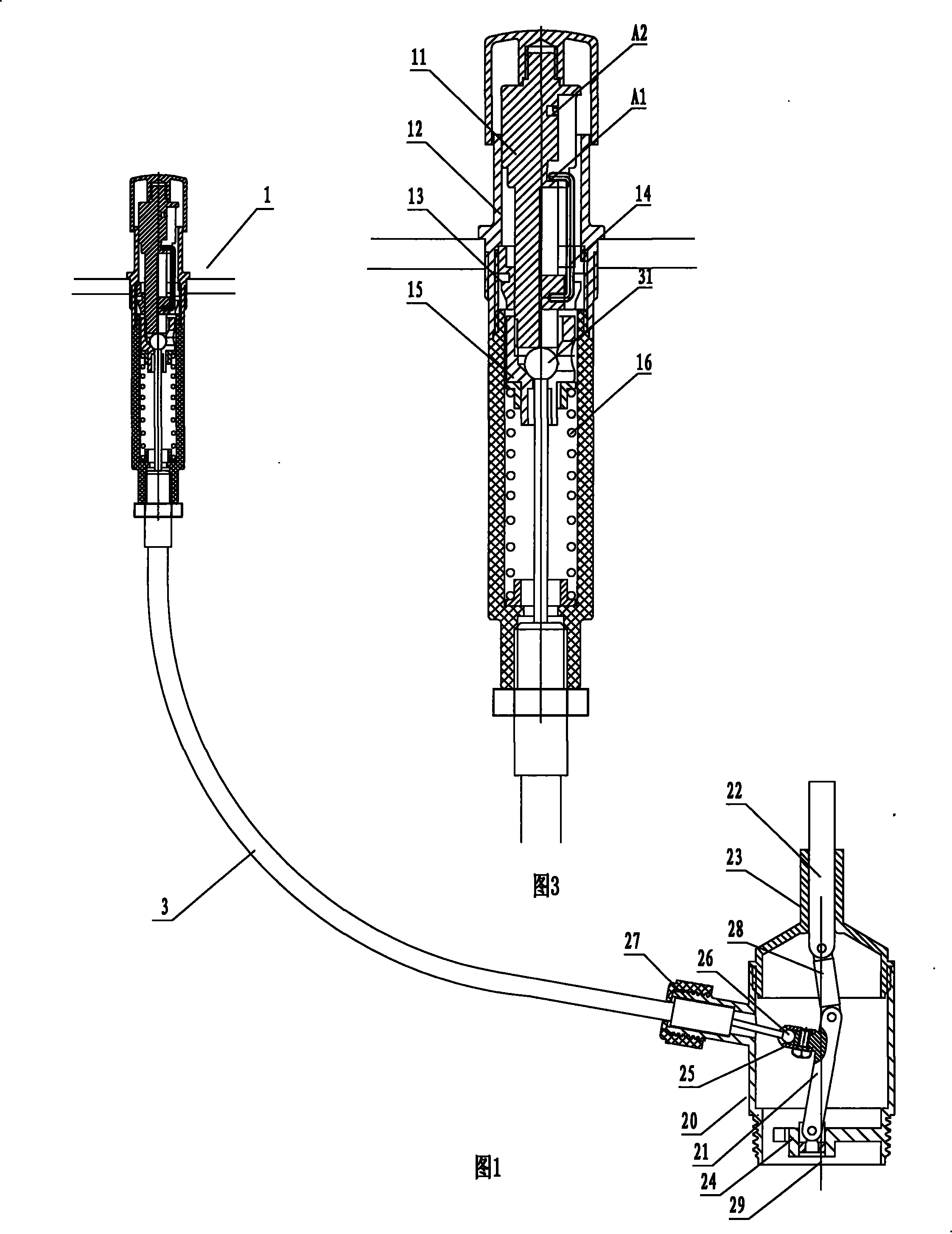

Image

  • Driving mechanism with positioning function
  • Driving mechanism with positioning function
  • Driving mechanism with positioning function

Examples


Embodiment 1

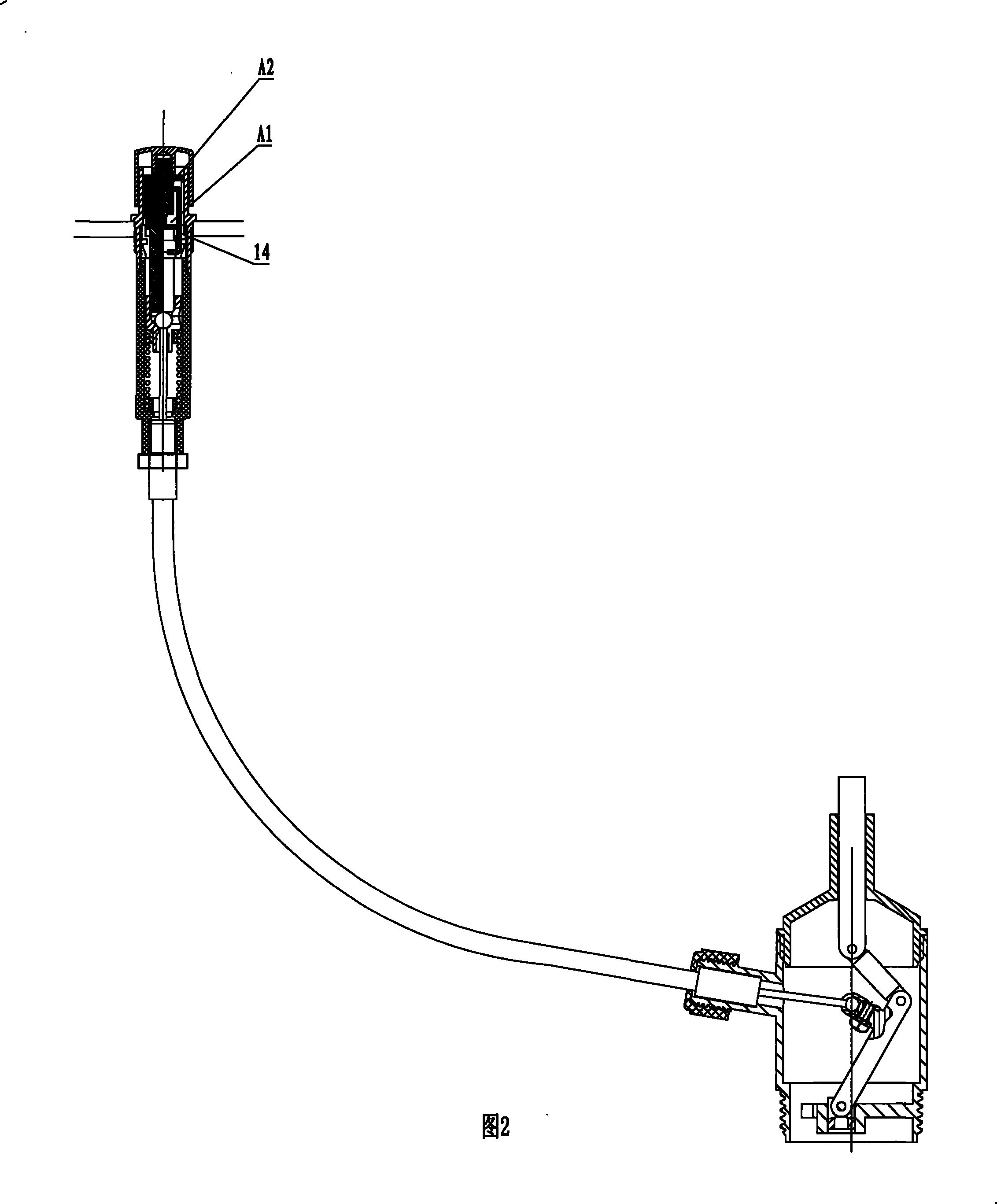
[0010] Refer to attached figure 1 , 2 , 3. The present invention includes a push-type switch 1. The switch is provided with a sliding shaft 11 and a fixed sleeve 12 penetrating up and down. The sliding shaft 11 can slide in the fixed sleeve 12. Generally, the operation of the sliding shaft is realized by pressing. In the axial direction of the sliding shaft, the sliding shaft is provided with two limiting positions A1 and A2 at different heights, which are formed by grooves penetrating the surface of the sliding shaft, and a plunger 13 is fixed inside the fixed sleeve 12, The fixed sleeve 12 and the plunger 13 can be a unified body, or parts that can be set separately, and the plunger 13 is fixed with a retaining hook 14, such as figure 1 , 2 As shown, when the sliding shaft is pressed to slide in the fixed sleeve in the axial direction, the hook part of the stop hook also slides in the groove. When the hook part of the stop hook is hooked at the limit position A1, the coop...

Embodiment 2

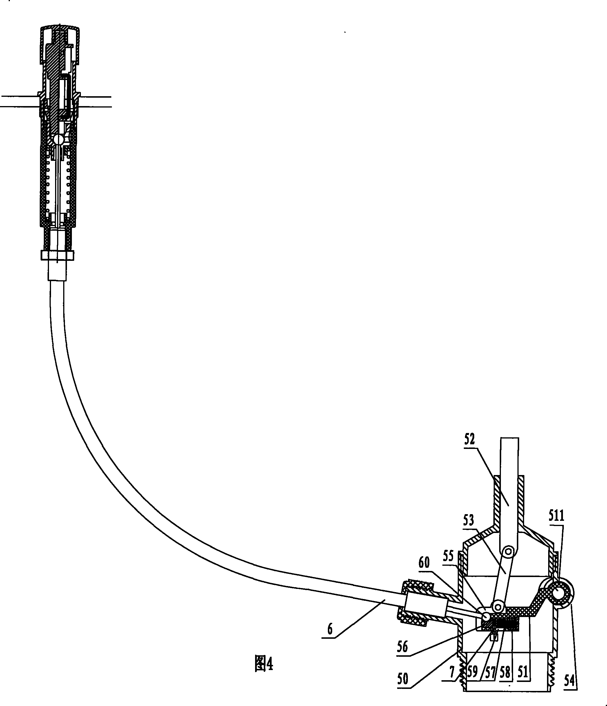
[0020] Refer to attached Figure 4 , 5 . In this embodiment, the connection scheme of the linkage mechanism, the installation body and the connecting steel wire is changed, and the others are the same as in Embodiment 1.

[0021] The connecting rod mechanism is also provided with an intermediate connecting rod 53 between the first connecting rod 51 and the second connecting rod 52, and the mounting body 50 of the connecting rod mechanism is provided with a connecting rod outside the side of the intermediate connecting rod 53 facing away from the connecting steel wire 6. The hinged connection seat 54 of the mechanism.

[0022] The end 511 of the first connecting rod is hinged on the hinged connecting seat 54, the head of the first connecting rod is provided with a connecting seat 55, and the end of the connecting steel wire is provided with a connecting head 60, and the connecting head is rotatably The card is set in the connecting seat.

[0023] The connecting seat is prov...


PUM


Abstract

The invention provides a driving mechanism with positioning function, which comprises a push-type switch, wherein the switch is provided with a sliding shaft and a fixed sleeve vertically running through, the sliding shaft can slide along the axial direction of the sliding shaft in the fixed sleeve, and the switch is also provided with two shifts along the axial direction of the sliding shaft. The driving mechanism is also provided with a connecting rod mechanism and a mounting body of the connecting rod mechanism, wherein the connecting rod mechanism comprises a first connecting rod and a second connecting rod; and the driving mechanism is provided with a guiding mechanism of the motion of the second connecting rod, and a connecting steel wire is arranged between the sliding shaft of theswitch and the first connecting rod. The driving mechanism organically combines the switch and the connecting rod mechanism and performs drive control by adopting pressing operations, the connecting rod mechanism can flexibly change the driving directions so that the driving mechanism can be effectively applied to a plurality of functional mechanisms in civil facilities, and the connecting rod mechanism is also suitable to be operated reversely; besides, in certain occasions, the driving mechanism can also be applicable to bidirectional operations from the side of the switch and from the sideof the connecting rod mechanism.

Description

technical field [0001] The invention relates to a transmission mechanism with positioning function. Background technique [0002] At present, in civil facilities, many functional mechanisms involve switching between two working states or position states, such as the opening and closing of boxes and cabinets, the opening and closing of drainage facilities, and so on. The common operation is to directly pull and turn to realize the switch, but this is very inconvenient in many occasions. There are also some switch devices, but the current switch devices, such as the operation switch of the drainage facility, are mostly of the pull-out type. On the one hand, the versatility is not enough, and the service life is short. On the other hand, it is difficult to cooperate with other mechanisms. Enhanced ease of operation, performance and application range. Contents of the invention [0003] The technical problem to be solved by the present invention is to provide a transmission m...

Claims


Application Information

Patent Timeline
Patent Type & Authority Patents(China)
IPC IPC(8): F16C1/10F16H21/04F16C1/20
Inventor 岑迪峰
Owner NINGBO BOSHENG PLUMBING CO
Learn More