
Connector device capable of meeting two-way transmission requirement of digital television

A two-way transmission and joint device technology, applied in the direction of cable transmission adaptation, clamping/spring connection, etc., can solve the problems of easy rust, noise, interference and other problems in the connection part, and achieve no noise interference, clear TV picture, and firm connection. Effect

Active Publication Date: 2011-06-22
桂林市创琳电子科技发展有限公司
View PDF0 Cites 2 Cited by
  • Summary
  • Abstract
  • Description
  • Claims
  • Application Information

AI Technical Summary

Problems solved by technology

[0002] The connecting device used in the existing TV receiving system, whether it is wireless satellite or cable, and whether it is analog TV or digital TV, it includes various wired cable connectors, patch cords, branches, distributors, user boxes , set-top boxes, various amplifiers, optical transmitters, receivers, etc., the F connectors and F connectors used have the following disadvantages: the TV signal line single-strand copper wire is twisted on the F head and the connection method is to rely on a thin hole in the product socket. The metal clip is connected by touch, the contact surface is very small, sometimes even the metal clip and the TV signal line are suspended from each other, the TV signal can only be transmitted by induction, and after a period of use, the connecting part is very easy to rust, so It is equivalent to connecting a resistor and a frequency mixing diode, which will generate noise and interference (distortion of the public road), reduce the signal-to-noise ratio of the TV picture, make the whole picture unclear, and even frequently appear mosaics, static frames, The error signal is interrupted or the image cannot be received

Method used


Image

  • Connector device capable of meeting two-way transmission requirement of digital television
  • Connector device capable of meeting two-way transmission requirement of digital television
  • Connector device capable of meeting two-way transmission requirement of digital television

Examples


Embodiment 1

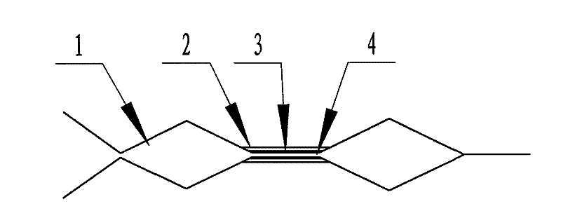
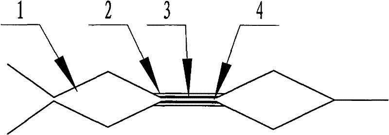
[0012] refer to figure 1 , the present invention consists of a phosphor copper sheet 2 wrapped around a cylindrical copper rod 3, the end of the cylindrical copper rod 3 is divided into two semi-cylinders, in the shape of a slightly opened bell mouth, and the centers of the two semi-cylindrical bodies are arranged symmetrically Slightly thinner than 1 / 2 the groove of the half-strand copper wire of the TV line, the symmetrical grooves form the clamping groove 4, and the part of the phosphor copper sheet 2 beyond the cylindrical copper rod 3 is equally divided into 3 pieces, from the middle of the excess part It is bent into an included angle greater than 90°, and its ends are closed to form a spindle-shaped gripper 1 .

Embodiment 2

[0014] refer to figure 2 , the present invention rolls the phosphor copper sheet 2 into a cylindrical shape, 4-12 holes are arranged at both ends of the cylindrical shape, and a dumbbell-shaped gripper 5 with a thin middle part and thick ends at both ends is arranged, and the hollow part of the dumbbell-shaped detailed part is a clamp Tight groove 4.


PUM


Abstract

The invention discloses a connector device capable of meeting two-way transmission requirement of a digital television. A metal sheet wraps a cylindrical copper rod, two ends of the cylindrical copper rod are arranged into two slightly-divided parts, the positions of a center of circle corresponding to the two parts are provided with grooves which are matched with TV signal wires, the grooves areclamping grooves, the metal sheet beyond the cylindrical copper rod is divided into three pieces and are arranged into a fusiform grabhook; or one metal sheet is rolled into a cylinder shape, two ends of the cylindrical metal sheet are arranged into grabhooks with a dumbbell shape with the thin middle part and two thick ends, and the thin part of the dumbbell shape is the clamping groove and is matched with the TV signal wire. The connector device can meet the two-way transmission requirement of the digital television, and has convenient, fast and firm connection, makes pictures clearer and more stable, and has no noise interference.

Description

technical field [0001] The invention relates to a joint device of a television system, in particular to a joint device capable of meeting the requirements of bidirectional transmission of digital television. Background technique [0002] The connecting device used in the existing TV receiving system, whether it is wireless satellite or cable, and whether it is analog TV or digital TV, it includes various wired cable connectors, patch cords, branches, distributors, user boxes , set-top boxes, various amplifiers, optical transmitters, receivers, etc., the F connectors and F connectors used have the following disadvantages: the TV signal line single-strand copper wire is twisted on the F head and the connection method is to rely on a thin hole in the product socket. The metal clip is connected by touch, the contact surface is very small, sometimes even the metal clip and the TV signal line are suspended from each other, the TV signal can only be transmitted by induction, and af...

Claims


Application Information

Patent Timeline
Patent Type & Authority Patents(China)
IPC IPC(8): H01R4/28H04N7/10
Inventor 莫胜林
Owner 桂林市创琳电子科技发展有限公司
Learn More