Floating double-axis synchronously moving mechanism

A floating, moving mechanism technology, applied in the field of laser repairing machines, can solve the problems that the two displacement devices cannot be started completely synchronously, the platform is pulled, and the force on the platform is uneven.

Inactive Publication Date: 2009-12-23
CONTREL TECH CO LTD
View PDF0 Cites 0 Cited by
  • Summary
  • Abstract
  • Description
  • Claims
  • Application Information

AI Technical Summary

Problems solved by technology

[0003] However, since the center of gravity of the bearing platform may shift due to uneven weight distribution, the two displacement devices cannot actually start completely synchronously; Because of being driven successively by the two displacement devices, a pulling effect is formed on the platform; in this way, the two ends of the platform may be stuck due to the uneven force at the moment of starting, so that the platform cannot Normal displacement along the track

Method used


Image

  • Floating double-axis synchronously moving mechanism
  • Floating double-axis synchronously moving mechanism
  • Floating double-axis synchronously moving mechanism

Examples


Embodiment Construction

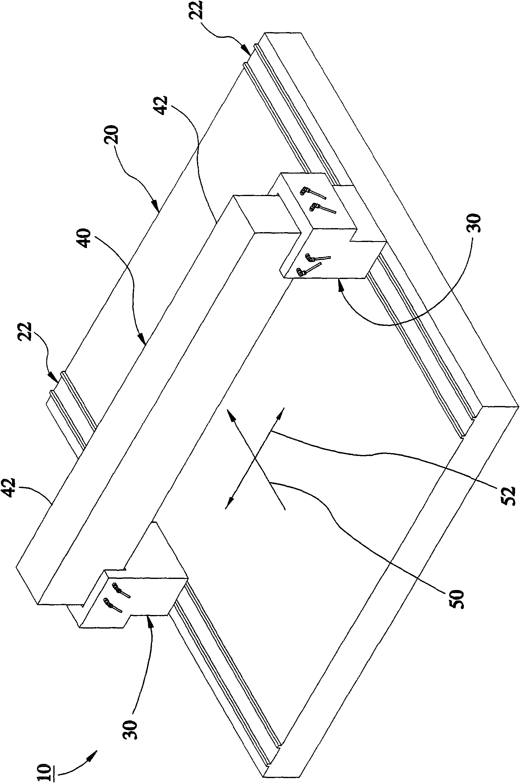
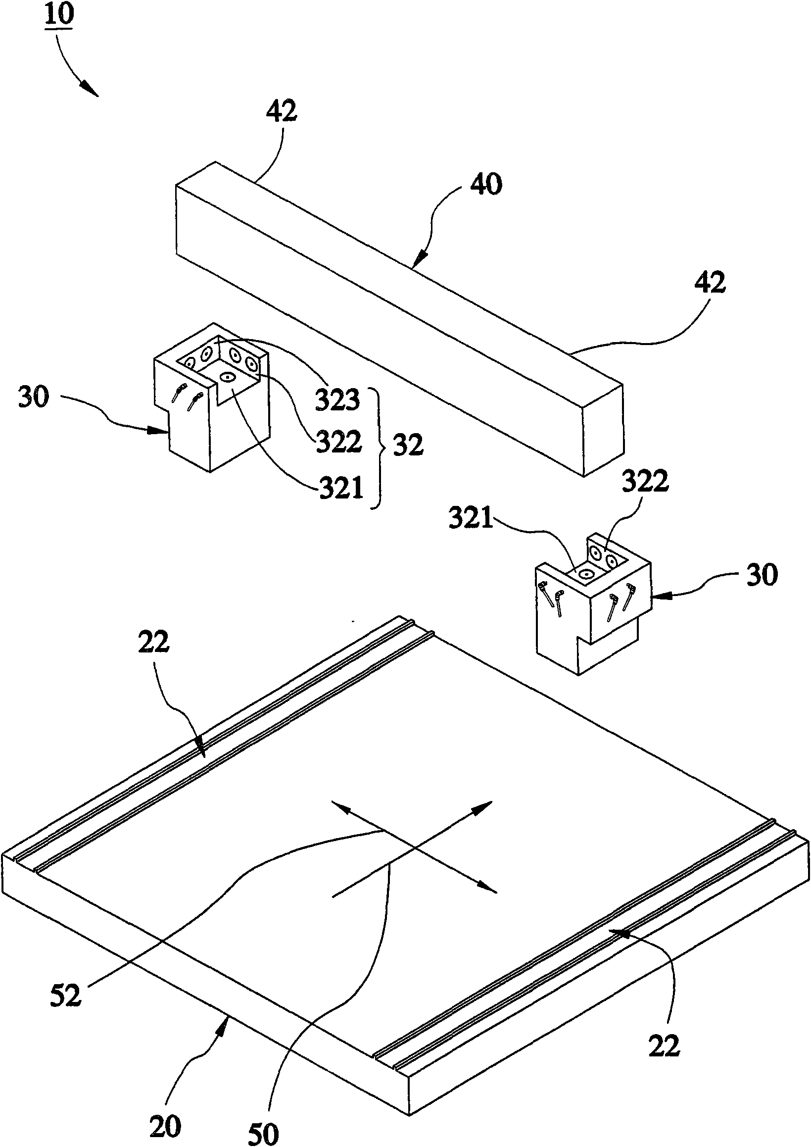
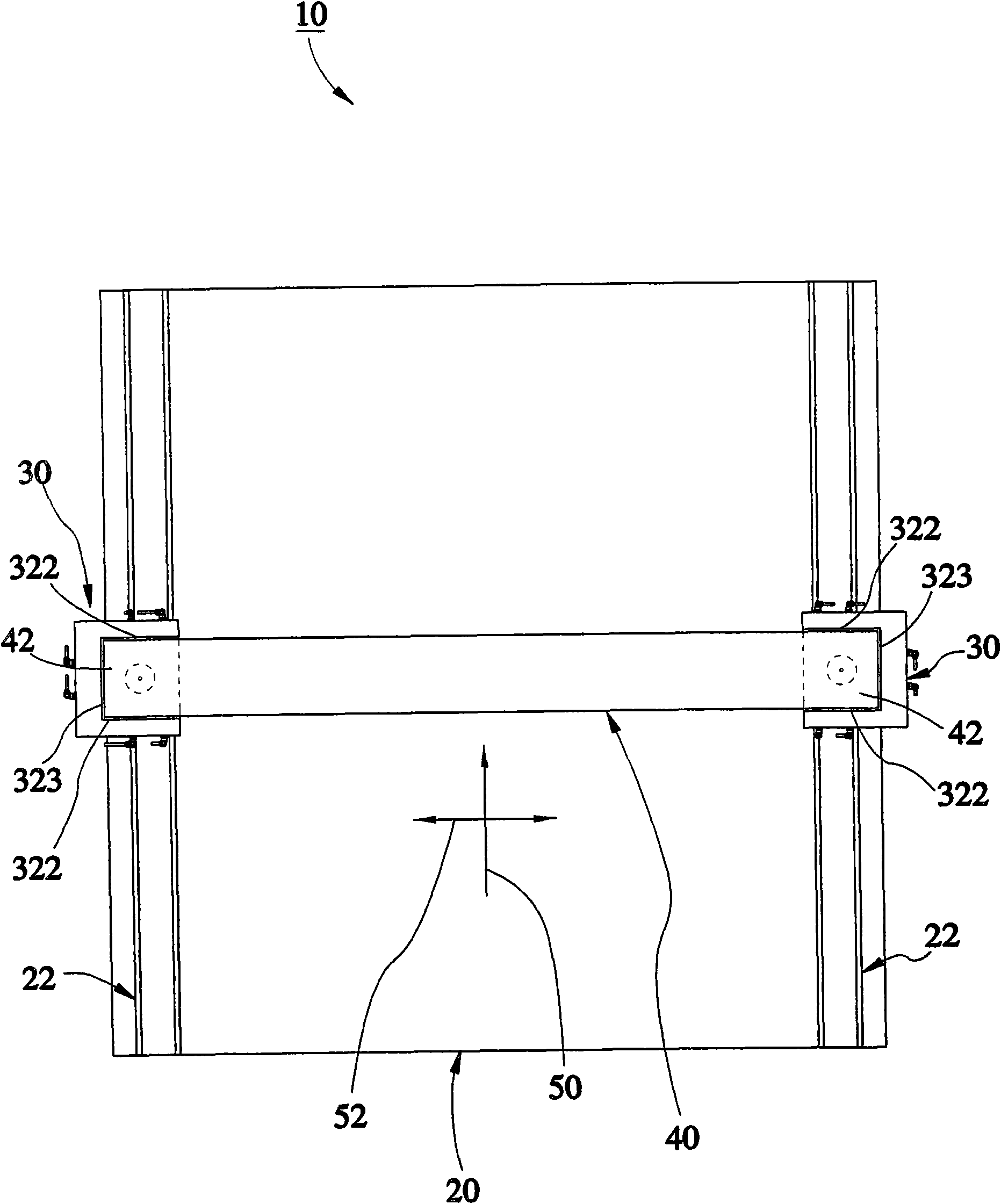
[0024] see Figure 1 to Figure 5 , a floating double-axis co-moving mechanism 10 provided in a preferred embodiment of the present invention includes a working platform 20 , a displacement device 30 and a platform 40 .

[0025] The working platform 20 has two rails 22 extending along an X-axis 50 , and the two displacement devices 30 are slidably mounted on the two rails 22 .

[0026] The two displacement devices 30 are respectively arranged on both sides of the working platform 20, and the displacement devices 30 can be displaced synchronously along the direction of the X-axis 50; each of the displacement devices 30 has a concave portion 32, and the concave portion 32 is defined along the direction of the X-axis 50 A bearing area 321 and two limiting areas 322; the bearing area 321 provides a vertical airflow; the two limiting areas 322 are located on both sides of the bearing area 321, and each of the limiting areas 322 provides two horizontal airflows; the two displacement ...


PUM


Abstract

The invention relates to a floating double-axis synchronously moving mechanism comprising a working platform, two displacement devices and a bearing platform. The two displacement devices are respectively arranged at both sides of the working platform and can synchronously move along the X axis direction; either displacement device is provided with a concave part which is defined into a bearing area and two limit areas along the X axis direction; the bearing area is provided with at least one vertical airflow, the two limit areas are respectively arranged at both sides of the bearing area, and either limit area is provided with at least one horizontal airflow; the bearing platform is provided with two end parts which are respectively arranged at the concave parts of the two displacement devices and can be pushed by the vertical airflow of the bearing area to float at the top side of the bearing area; and either end part can be pushed by the horizontal airflows of the limit areas to move along the X axis direction.

Description

technical field [0001] The invention relates to a laser repair machine, in particular to a floating double-axis co-moving mechanism for a laser repair machine. Background technique [0002] The prior art conveying mechanism for a laser repair machine has a platform, a platform, and two displacement devices; the displacement devices are respectively located at the bottom sides of the two ends of the platform and are arranged between the platform and the platform ; Through this, the platform is synchronously driven by the displacement devices to achieve the purpose of displacement along an X-axis direction. [0003] However, since the center of gravity of the bearing platform may shift due to uneven weight distribution, the two displacement devices cannot actually start completely synchronously; Because of being driven successively by the two displacement devices, a pulling effect is formed on the platform; in this way, the two ends of the platform may be stuck due to the une...

Claims


Application Information

Patent Timeline
IPC IPC(8): B23K37/00B23K37/02B23K26/00
Inventor 叶公旭苏纪为
Owner CONTREL TECH CO LTD
Why Eureka
Try Eureka