Energy dissipation device made of metal tube

A technology of energy dissipation device and metal pipe, applied in construction, protective equipment, etc., can solve problems such as stuck wire rope, wire rope wear, wire rope breakage, etc., and achieve the effect of solving complex mechanical mechanism, thorough deformation, and avoiding friction.

Pending Publication Date: 2018-05-04
重庆天衢通辉科技发展有限公司 +1
View PDF17 Cites 0 Cited by
  • Summary
  • Abstract
  • Description
  • Claims
  • Application Information

AI Technical Summary

Problems solved by technology

[0005] 1. There are two steel wire ropes in each aluminum tube, and there will be friction between the ropes during the movement, which will cause the wear of the steel wire rope and cause the breakage of the steel wire rope;
[0006] 2. Since the energy consumed by the friction of the two wire ropes cannot be measured, the working status is not clear, and it is impossible to select suitable energy dissipation parts during use;
[0007] 3. During the deformation process of the aluminum tube, on the one hand, the folds produced by the plastic deformation of the aluminum tube may jam the steel wire rope; , it is easy to cause incomplete deformation of the aluminum tube, and the energy dissipation parts cannot fully play the role of energy absorption

Method used


Image

  • Energy dissipation device made of metal tube
  • Energy dissipation device made of metal tube
  • Energy dissipation device made of metal tube

Examples


Embodiment 1

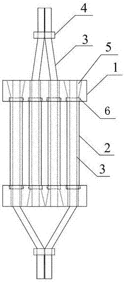
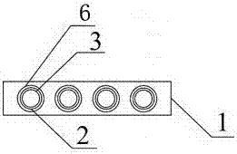
[0023] Such as figure 1 and figure 2 As shown, this embodiment includes a fixing part 1, a metal pipe 2, a steel wire rope 3, a wire clip 4 and a clip 5. The fixing part 1 is a rectangular metal block with two sets of symmetrical countersunk through holes 6. The two fixing parts 1 Relatively insert the metal pipe 2 in the countersunk groove, and the countersunk groove of the countersunk through hole 6 is used to restrain the end of the metal pipe 2;

[0024] The steel wire rope 3 enters through the countersunk through hole 6 of a fixing piece, passes through the metal pipe 2, and one end of the steel wire rope 3 is anchored in the through hole of the countersunk through hole 6 of the other fixing piece 5 through the clip 5; from one of the fixing pieces 1 A set of symmetrical countersunk through-holes 6 lead out steel wire ropes 3 , and a group of steel wire ropes 3 drawn out from the outside of the fixing part 1 are merged and connected together by wire clips 4 .

[0025] ...

Embodiment 2

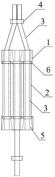
[0027] Such as image 3 and Figure 4 As shown, the difference between this embodiment and Embodiment 1 is that the fixing member 1 is a circular metal block with two sets of symmetrical countersunk through holes, and the symmetrical countersunk through holes are evenly distributed on the circumference.

[0028] It is not difficult to imagine that the fixing member 1 can also be a square metal block with two sets of symmetrical countersunk through holes, and the symmetrical countersunk through holes are evenly distributed on the diagonal.

[0029] In the above embodiment, there are only two symmetrical countersunk holes. Of course, the number of countersunk holes may be three or more to form a symmetrical group of symmetrical countersunk holes.

[0030] The fixing part 1 mainly plays the role of fixing and positioning. There are symmetrical metal pipes between the fixing parts. The fixing part 1 has two sets of symmetrical countersunk through holes 6. The through holes of th...


PUM


Abstract

The invention discloses an energy dissipation device made of a metal tube. The device comprises fixing pieces (1), the metal tube (2), steel wire ropes (3), a wire clamp (4) and a clamping piece (5),wherein each fixing piece (1) is a metal block provided with two sets of symmetric countersunk through holes (6), and the two fixing pieces (1) make the metal tube (2) embedded in countersunk groovesoppositely; the steel wire ropes (3) enter the device from the countersunk through holes of one fixing piece and penetrate through the metal tube (2), and one end of each steel wire rope (3) is anchored into the corresponding countersunk through hole (6) of the other fixing piece (1); one steel wire rope (3) is led out from one set of symmetric countersunk through holes (6) in the other fixing piece (1) and combined with the other steel wire rope (3) led out from the outer side of the fixing piece (1), and the steel wire ropes are connected through the wire clamp (4). The device solves the problems that in an existing energy dissipation element, a metal tube is not thorough in deformation, unstable in performance and unclear in work state.

Description

technical field [0001] The invention belongs to the technical field of safety protection, and in particular relates to an energy dissipation device for absorbing and slowing down impact loads in steel wire ropes in a passive flexible protection system for intercepting rockfall on a side slope. Background technique [0002] The passive flexible protection system is mainly composed of intercepting components (wire rope net and ring net), fixing system (anchor, anchor rope, base, steel column and support rope) and energy dissipation devices, and its anti-rockfall impact ability is mainly composed of intercepting components Provided by the elastic-plastic deformation of the energy dissipation device, the energy dissipation device also has the function of overload protection for the entire passive flexible protection system. Therefore, the stability of the energy dissipation device is extremely important for the passive flexible protection system. [0003] Chinese patent document...

Claims


Application Information

Patent Timeline
Patent Type & Authority Applications(China)
IPC IPC(8): E01F7/04
CPCE01F7/045
Inventor 石泽玮石少卿王文康
Owner 重庆天衢通辉科技发展有限公司
Why Eureka
Try Eureka