Micropump

A technology of micro-pumps and valve membranes, which is applied to pumps, pump components, variable-capacity pump components, etc., which can solve the problems of unfavorable mass industrial production, and it is difficult to ensure that the input check valve and output check valve 15 are well closed.

Inactive Publication Date: 2009-12-23
SHANGHAI MICROPORT MEDICAL (GROUP) CO LTD
View PDF0 Cites 14 Cited by
  • Summary
  • Abstract
  • Description
  • Claims
  • Application Information

AI Technical Summary

Problems solved by technology

Since the input check valve 14 and the output check valve 15 are semi-floating check valves, when the pressure difference between the input passage 13 and the output passage 16 is not large, it is difficult to ensure that the input check valve 14 or the output check valve 15 well closed
At the same time, in order to ensure the tight sealing of the two one-way valves, the processing accuracy of the valve plate and the corresponding plane is generally very high, which is not conducive to mass industrial production

Method used


Image

  • Micropump
  • Micropump
  • Micropump

Examples


Embodiment Construction

[0050] The invention provides a micropump for realizing reliable control of an input check valve and an output check valve.

[0051] In order to enable those skilled in the art to better understand the solution of the present invention, the present invention will be further described in detail below in conjunction with the accompanying drawings and specific embodiments.

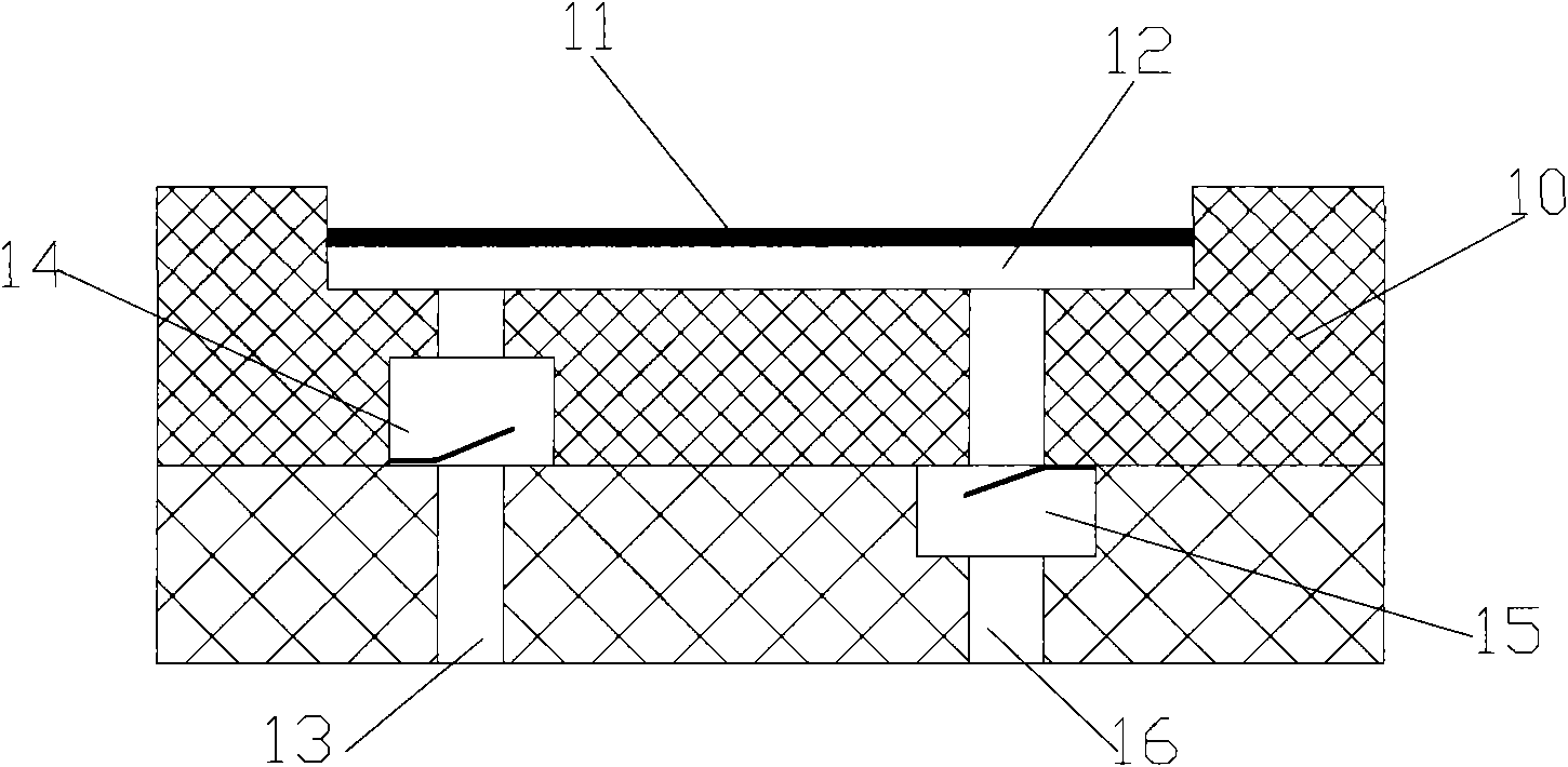
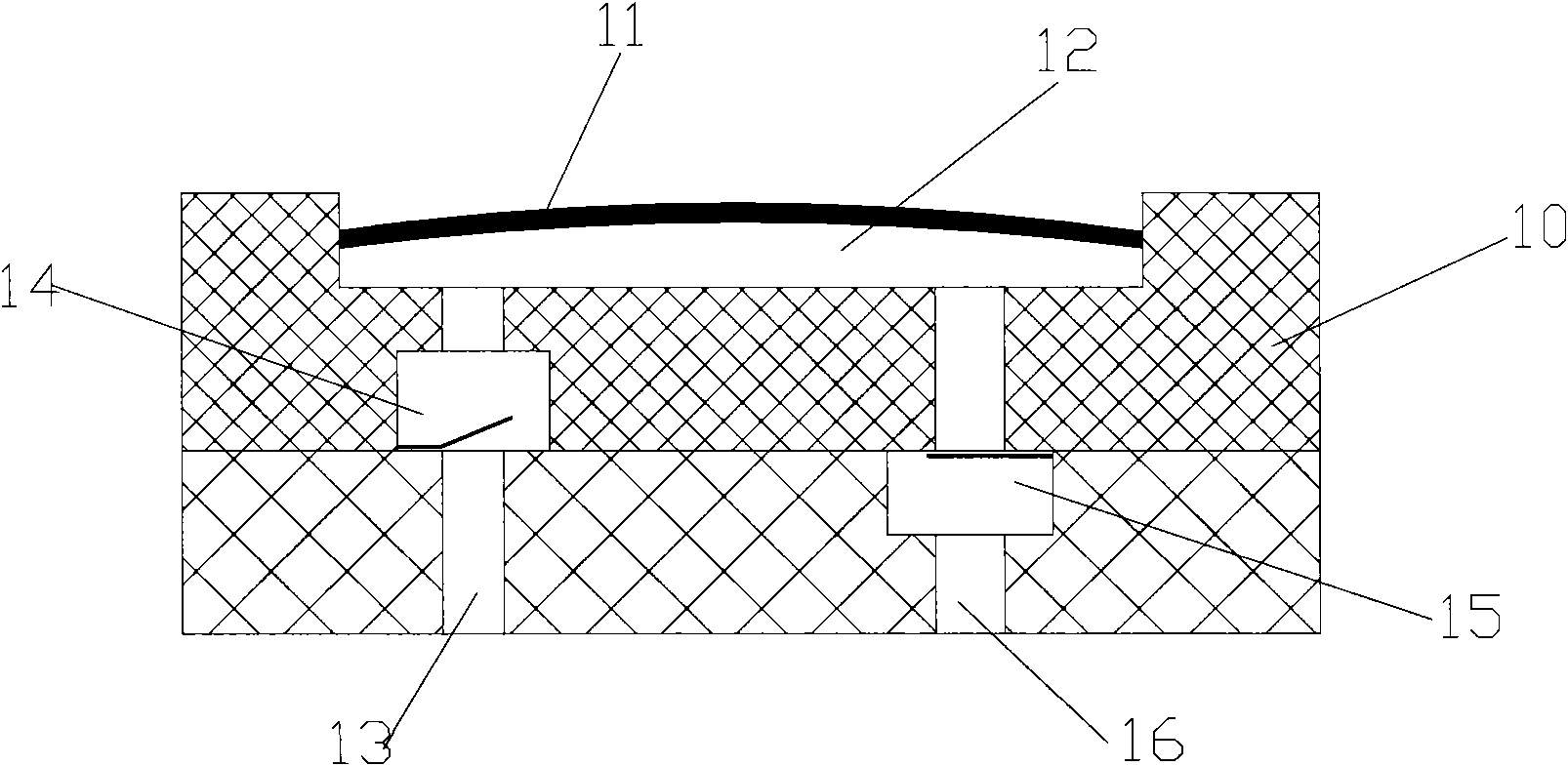
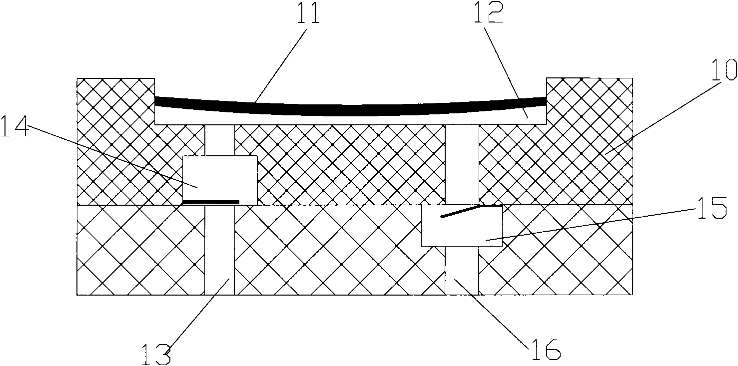
[0052] see Figure 4 and Figure 5 , Figure 4 It is the structural diagram of the first embodiment of the micropump according to the present invention; Figure 5 for Figure 4 Sectional view A-A is shown.

[0053] The micropump described in the first embodiment of the present invention includes an actuating device, a space-variable cavity 2 , and an input channel and an output channel respectively connected to the space-variable cavity 2 . A valve membrane 7 that responds to the action of the actuating device is installed in the input channel and the output channel.

[0054] The micropump specifically ...


PUM


Abstract

The invention discloses a micropump, which comprises an actuating device, a space variable cavity, and an input channel and an output channel which are connected with the space variable cavity respectively, wherein a valve diaphragm which responds to the action of the actuating device is arranged in the input channel and / or the output channel. The micropump provided by the invention is used for realizing the reliable control of an input one-way valve and an output one-way valve; and the valve diaphragm can exert prestress to ensure that the input one-way valve and the output one-way valve are opened and closed effectively under the condition that the contact surface between the input channel and the output channel and the valve diaphragm has low manufacturing accuracy.

Description

technical field [0001] The invention relates to a pump, in particular to a micropump. Background technique [0002] Existing micropumps, including piezoelectric ceramic pumps. refer to figure 1 , figure 1 It is a structural diagram of an existing piezoelectric ceramic pump. The existing piezoelectric ceramic pump 10 includes a piezoelectric ceramic sheet 11 (sometimes referred to as piezoelectric ceramic), a variable space cavity 12 , an input channel 13 , an input check valve 14 , an output check valve 15 , and an output channel 16 . [0003] The piezoelectric ceramic sheet 11 can be in the shape of a multilayer disc, and the base material of the piezoelectric ceramic sheet 11 can be made of copper or stainless steel. material, the conductive material may be silver. The base material and the conductive material covered on the piezoelectric ceramic material are respectively connected to two poles of an AC power supply. After electrification, due to the property of the ...

Claims


Application Information

Patent Timeline
Patent Type & Authority Applications(China)
IPC IPC(8): F04B43/00F04B53/10A61M5/142
CPCF04B43/043
Inventor 罗七一王勤曾志海刘宇程杨平中
Owner SHANGHAI MICROPORT MEDICAL (GROUP) CO LTD
Why Eureka
Try Eureka